Your Minn Kota 11-character serial number is very important…it helps to determine the specific model and year of manufacture.& Minn Kota produce a wide range of products so the serial number location may vary.
If you need assistance in locating the serial number on a product, please use this reference sheet.
When contacting Consumer Service&or registering your product, you will need to know your product’s serial number.& We recommend that you write the serial number down in your product’s user manual&or somewhere outside of your boat so you have it available&for future reference.
Serial number formats may include MKAD1234567 or J123MK12345&
Examples:
Talon Shallow Water Anchors The serial number is located under the motor housing.
Ulterra and Riptide Ulterra Bow-Mount Trolling Motors&The serial number is located inside the mount near the motor rests, this can be seen when the motor is stowed.The i-Pilot or i-Pilot Link, serial number is located on the opposite side of the mount.
Terrova and Riptide Terrova Bow-Mount Trolling MotorsThe serial number is located inside the mount near the motor rests, this can be seen when the motor is stowed.If pre-installed with i-Pilot or i-Pilot Link, the serial number is located on the opposite side of the mount.
PowerDrive V2 and Riptide PowerDrive Bow-Mount Trolling MotorsThe serial number is located inside the mount near the motor rests, this can be seen when the motor is stowed.If pre-installed with i-Pilot, the serial number is located on the opposite side of the mount.
Fortrex, Maxxum and Edge Bow-Mount Foot Control Trolling MotorsThe serial number is located near the momentary switch underneath the side of the foot pedal.
Endura C2 Transom Mount Trolling MotorsThe serial number is located on the top of the transom bracket.
Traxxis Transom Mount Trolling MotorsThe serial number is located under the tiller handle.
On-Board Battery ChargersThe serial number is located on the input AC cord and the bottom of the charger.
i-Pilot and i-Pilot Link Wireless GPS Trolling System AccessoriesThe serial number is located underneath the control box cover, it will have a UM designation.
Minn Kota Electric Bow Mount Trolling Motors are available in various voltages, thrust ratings and shaft lengths. There are also different model configurations within these sizes. The most popular models available in Australia are as follows:
Riptide Saltwater Bow Mount Models with I-Pilot
Minn Kota ST (Saltwater Terrova) model is supplied standard with i-Pilot. i-Pilot frees you up to focus on fishing. It uses GPS technology to remember paths and fishing spots on the water, activate cruise control, and give you command of speed, steering and Advanced AutoPilot. i-Pilot will give you unprecedented navigation and boat positioning. IPilot available in 55lb, 80lb and 112lb thrust levels.
RT55ST – Minn Kota Riptide Terrova 54” 12 Volt 55lb I-Pilot (601470)
IPilot remote control
Ability to add a foot pedal
RT80ST – Minn Kota Riptide Terrova 54” 24 Volt 80lb I-Pilot (601474)
IPilot remote control
Ability to add a foot pedal
RT80ST – Minn Kota Riptide Terrova 60” 24 Volt 80lb I-Pilot (601476)
IPilot remote control
Ability to add a foot pedal
RT112ST – Minn Kota Riptide Terrova 60” 36 Volt 112lb I-Pilot (601478)
IPilot remote control
Ability to add a foot pedal
Minn Kota SP (Saltwater Powerdrive) model is optimized for saltwater performance with Riptide® SP’s re-engineered electric steer control, new deploy-assist lever, and a host of features that set the standards for power and control. Now standard with i-Pilot. Deploy-Assist Lever. Riptide® SP’s deploy-assist lever puts you in motion and in pursuit of fish quickly and easily. When you depress the lever, the motor deploys and you’re ready to go. When it’s time to move, it stows easily and securely – ready for action whenever you are. I-Pilot available in 55lb and 70lb thrust levels.
RT55SP – Minn Kota Riptide Terrova 48” 12 Volt 55lb I-Pilot (601454)
IPilot remote control
Can’t add a foot pedal
RT70SP – Minn Kota Riptide Terrova 54” 24 Volt 70lb I-Pilot (601462)
IPilot remote control
Can’t add a foot pedal
Minn Kota Freshwater Ulterra With I-Pilot model comes with your choice of i-Pilot or i-Pilot Link, a redesigned foot pedal and Universal Sonar 2. Advanced wireless remote uses GPS to remember fishing spots and paths, and can control speed, steering, cruise control and Advanced AutoPilot. And exclusively on i-Pilot for Ulterra, three new buttons let you stow and deploy your motor, or trim it up and down.
Minn Kota Ulterra 80 US2 Freshwater I-Pilot Bow Mount Electric Trolling Motor – 60 inch 24 Volt 80lb Thrust (601752)
AUTO STOW DEPLOY – Auto Stow/Deploy lets you get your motor in and out of the water automatically using the included i-Pilot or i-Pilot Link remote, or the redesigned foot pedal.
POWER TRIM – Once your motor’s in the water, Power Trim lets you easily adjust the motor depth for changing conditions, using the included i-Pilot or i-Pilot Link remote, or the redesigned foot pedal.
Integrated GPS Technology – All Ulterra models come with your choice of either i-Pilot or i-Pilot Link, with additional functionality that lets you control features like Auto Stow / Deploy and Power Trim.
Auto Stow/Deploy and Power Trim
Minn Kota Ulterra 80 US2 FRESHWATER I-Pilot Bow Mount Electric Trolling Motor – 60 inch 24 Volt 80lb Thrust – Incl. Foot Pedal (601752)
Minn Kota Riptide Ulterra 80 IPilot SALTWATER Bow Mount Electric Trolling Motor – 60 inch 24 Volt 80lb Thrust (601756)
Minn Kota Riptide Ulterra 112 IPilot SALTWATER Bow Mount Electric Trolling Motor – 60 inch 36 Volt 112lb Thrust (601758)
Minn Kota Riptide Ulterra 112 IPilot SALTWATER Bow Mount Electric Trolling Motor – 72 inch 36 Volt 112lb Thrust (601760)
Trolling Motor Shaft Length Guide
Selecting the proper shaft length is critical. You want to make sure the motor’s shaft is long enough to keep the propeller submerged in varying water conditions, but not so long that it catches on the bottom or is a hassle to stow.
Transom Mount Shaft Length
Shaft length on transom mount motors is less critical than on bow mount motors, but is still important to double-check.
Proper shaft length selection is more critical with bow mount motors (as compared to transom mount). Bow-to-water distances tend to vary more from boat to boat, and the bow moves much more on the water than the transom. As such, it’s important to make sure you select the proper shaft length. Start by measuring the distance from the horizontal mounting point on the bow to the waterline, then add 20” to this measurement (24” for Ulterra motors). Generally, you will want a shaft length that is equal to or greater than this sum, but not less. The following factors may be further considerations:
If you frequently fish in rough waters: Then add 5” to the recommended lengths below. This will help the propeller stay submerged despite the additional deck bob of choppy or windy waters.
If steering a hand controlled motor standing up: Then add 12” to the recommended transom lengths below. This will make it easier and more comfortable to steer by bringing the motor tiller higher up.
Transom Mount Shaft Length
Shaft length on transom mount motors is less critical than on bow mount motors, but is still important to double-check.
A Few Rules to Remember
Submersion Rule: You’ll want the center of the propeller submerged at LEAST 9” under the water to ensure adequate power and to prevent noisy cavitation which will scare fish. The charts above will help you determine what shaft length achieves this (given different distances to the water, the shaft portion above the mount, etc) but it’s still a good idea to keep this 9” figure in mind.
Always Go Long: If you’re struggling to decide between two lengths, pick the longer one. If the shaft ends up being a bit too long, you can always adjust the shaft depth upward with the depth collar adjustment found on nearly all trolling motors. But if you pick a shaft that’s too short, you’re simply out of luck.
How the Shaft is Measured
If you’re trying to determine how long your existing shaft is – or take measurements on your own boat – it’s helpful to know exactly how the shaft is measured. Shaft measurements are taken from the base of the motor head to top of the propeller housing, as seen below:
ADDING / REMOVING REMOTES
THE RECEIVER MUST “LEARN” THE ID NUMBER OF ANY ADDITIONAL REMOTE(S) THAT YOU INTEND TO USE. WHEN THE RECEIVER LEARNS THE ID NUMBER OF A REMOTE, THAT ID NUMBER IS RETAINED IN THE RECEIVER EVEN WHEN THE MOTOR IS DISCONNECTED FROM ITS POWER SOURCE.
To “learn” the ID number of additional remotes, follow these steps:
The system ready light must be on. To do so; push in the release handle and rotate it down.
Press and hold the LEARN button located on the side of the receiver (receiver will emit a continuous tone.) A small blunt object must be used to depress the LEARN button ( pen or screwdriver.)
Press any button on the remote (receiver will beep 4 times confirming that it has “learned” the ID number of the remote and that the programming is valid and complete.)
“Re-learning” the ID number of the same remote will not overwrite previously “learned” remotes.
If the receiver has “learned” the ID number of ten remotes, “learning” an eleventh remote will erase or over write the first “learned” remote.
The CoPilot allows the angler to erase all stored remote ID numbers from the receiver.
To do so, follow these steps:
Remove power from the receiver by stowing the motor.
Press and hold the LEARN button and power up the receiver by pushing in the release handle and rotate it down. Hold the LEARN button down for 10 seconds. During this time the receiver audio will emit a warble sound, slowly transition to a constant beep and then shut off.
Release the Learn button and the receiver will reboot. The receiver will emit a 2 second long beep indicating memory is empty. This audio pattern will occur each time the receiver powers up until a remote ID number is learned.
Minn Kota Bow Mount Motor Options and Accessories:
Minn Kota Quick Release Bow Mount Bracket Add a quick release bracket to your installation for quick and easy removal of your minkota motor for security or for travel.
Minn Kota Foot Pedal (corded) Operate your minnkota motor while you have your hands full with the fish. This becomes a ‘must-have’ when fishing alone and you don’t have an off-sider to operate the remote control.
2.5m Electric Trolling Motor Wiring Loom Prefabricated with conduit and battery lugs – includes waterproof Circuit Breaker and High Amp Waterproof thru-deck plug/socket. All installations should include a waterproof circuit breaker for isolation when charging or storage, and a waterproof plug/socket for the convenient removal of your Min Kota. These wiring looms are fast to install and save money. Just add to your battery terminals and mount the thru-deck plug/socket and your ready to plug in.
5.0m Electric Trolling Motor Wiring Loom Prefabricated with conduit and battery lugs – includes waterproof Circuit Breaker and High Amp Waterproof thru-deck plug/socket. All installations should include a waterproof circuit breaker for isolation when charging or storage, and a waterproof plug/socket for the convenient removal of your Min Kota. These wiring looms are fast to install and save money. Just add to your battery terminals and mount the thru-deck plug/socket and your ready to plug in.
Marinco Heavy Duty 40A Minn Kota Thru-Deck Plug/Socket High Amp Waterproof thru-deck plug/socket. All installations should include a waterproof circuit breaker for isolation when charging or storage, and a waterproof plug/socket for the convenient removal of your Min Kota.
BEP 50A Heavy Duty Waterproof Circuit Breaker – Surface Mount Waterproof Circuit Breaker – all installations should include a waterproof circuit breaker for isolation when charging or storage. Protects the wiring and electric motor.
BEP 50A Heavy Duty Waterproof Circuit Breaker – Panel Mount Waterproof Circuit Breaker – all installations should include a waterproof circuit breaker for isolation when charging or storage. Protects the wiring and electric motor.
Voltage Sensitive Relay (VSR) 12 Volt 125 Amp
For charging second 12 Volt battery automatically from 12 Volt starting battery.
Safely charge two or more independent battery banks from one charge source (alternator, battery charger, solar…)
Charges engine starting batteries before combining auxiliary bank for charging
Protects start batteries from becoming flattened by domestic loads
Isolates electronics from harmful electrical surges from starter motors
Simple to install 3 wire connection, leaves alternator wiring intact
No volt drop vs. diode isolators
Ignition protected
Surface or panel mountable
Pro Charge 12VDC–12VDC Waterproof Battery Charger Connect this between your start battery and your minn kota battery bank to charge your 12 Volt house or Minn Kota battery system automatically from 12 Volt starting battery. Simply connect the input cables to a 12V starting battery, and connect output cables to the Minn Kota battery or bank of batteries. The Pro Charge-B will take care of the rest with multi-stage battery charging that will go to true bulk, absorption and float voltages. Fully waterproof.
Pro Charge 12VDC–24VDC Waterproof Battery Charger Connect this between your start battery and your min kota battery bank to charge your 24 Volt house or Minn Kota battery system automatically from 12 Volt starting battery. Simply connect the input cables to a 12V starting battery, and connect output cables to the 24V Minn Kota battery or 24V bank of batteries. The Pro Charge-B will take care of the rest with multi-stage battery charging that will go to true bulk, absorption and float voltages. – for charging 24 Volt battery system automatically from 12 Volt starting battery. Fully waterproof.
Pro Charge 12VDC–36VDC Waterproof Battery Charger Connect this between your start battery and your minn kota battery bank to charge your 36 Volt house or Minn Kota battery system automatically from 12 Volt starting battery. Simply connect the input cables to a 12V starting battery, and connect output cables to the 36V Minn Kota battery or 36Volt bank of batteries. The Pro Charge-B will take care of the rest with multi-stage battery charging that will go to true bulk, absorption and float voltages. – for charging 36 Volt battery system automatically from 12 Volt starting battery. Fully waterproof.
Deka Intimidator 8A31DTM Battery For this job you need a well built, heavy duty cycling battery that can handle heavy discharge and re-charge… repeatedly. Chinese batteries just won’t do the job. Use Deka 8A31DTM 12 Volt / 105Ah / AGM / 800CCA – Quality USA made batteries – heavy duty. Use two in parallel for extra 12 volt power or use them in series for your 24V and 36V Minn Kota needs.
Large Battery Box to suit Deka Intimidator 8A31DTM 105Ah AGM battery
Spare or Replacement Minn Kota I-Pilot Remote Control What do you do if your fishing buddy hooks up and they have the remote? Use your own. You can program up to 10 remotes to operate the same Minn Kota. Don’t go fishing without one remote each, it no time to juggle remotes, rods, drinks etc. when your hooked up!
Frequently Asked Questions on Shakespeare VHF Marine Antennas, CB Antennas, Marine TV Antennas, Marine Cellular Antennas, CB Antennas, Phase III Series Antennas and General questions
General Questions
Do I lose anything by using a Combination antenna?
Yes, usually – depending on the type and quality of combination antenna. Generally reception performance for the VHF side is somewhat sacrificed. Shakespeare recommends using separate antennas if space is available for them.
Is it better to use a dedicated AM/FM antenna or a band separator?
Shakespeare recommends using a separate antenna for this purpose, if possible. Band separators were designed for boats that don’t have room for two antennas. Be sure the antennas are mounted at least three feet apart.
What is antenna gain, and how is it measured?
Gain is an increase in effective radiated power (ERP) from an antenna, usually stated in dB (deciBels). As a rule of thumb, you can multiply the radio’s output power by 4 for 6dB antennas and by 8 for 9dB antennas. A 3dB antenna gain gives an ERP of 2 times the radio’s output power. A Unity Gain antenna provides no increase in ERP.
Can I paint the antenna, and with what?
Yes. Shakespeare’s antennas can be painted any color you wish. Be sure not to use any paint containing metallic chips or lead bases. To prepare the surface, wash the antenna with soap and water and allow it to dry completely. Paint the antenna with polyurethane or a lead free, non-metallic paint.
Can I repair the antenna if the fiberglass becomes frayed?
Yes. Wash the antenna with soap and water first and allow it to dry completely. Next, paint the antenna with polyurethane or a lead free, non-metallic paint. Then lightly sand the surface with 400-grit sandpaper. Additional coats of paint may be added, but are usually not really necessary.
What is the transmission line loss for coax?
This depends on the amount, as well as the type of coax used. On the average, 50 feet of RG-58 coax will have about 3dB loss, 50 feet of RG-8X coax will have about 2dB loss, and 50 feet of RG-213 (RG-8U) will have about 1dB loss.
What antenna should I use with what radio?
It depends on your needs and the amount of space that is available to mount the antenna. Some considerations are: the height at which you can mount the antenna; whether you have to raise and lower it to fit under bridges, boathouses or other obstructions; and how far you need the transmitted signal to reach. The longer the antenna, the better coverage you can expect, generally speaking, if a larger antenna will fit on your boat. Always purchase the best antenna you can afford, since the antenna is the most important part of any VHF installation.
Can I use two radios with one antenna?
Yes, Shakespeare offers the CS-2 and AS-2 switches, which allow for hook-ups of this nature. The CS-2 switch permits using two antennas with one radio, or two radios with one antenna. The AS-2 is an automatic switch for two radios connecting to one antenna. It electronically senses which transceiver is used and switches the antenna. Further instructions are on the packages.
What is meant by DC ground?
Some antennas are DC grounded and will indicate a short circuit when tested with an ohm meter. Antennas which do not use DC Grounding generally read as Open circuit on an Ohm meter
Do I need a license from the FCC? If so, how do I get one?
For non-commercial boaters using vessels which are not required to have ship’s radio stations, no FCC license is required for local cruising. “Local” means USA waters only. If you cruise and sail into foreign waters of Canada, Mexico, and the Caribbean, you must have an FCC issued license and callsign. Also, mariners who operate a marine SSB and/or INMARSAT phone must have an FCC issued callsign. The FCC callsign is also required for a marine “Sailmail” e-mail address. If you have marine single sideband (SSB) radio onboard, or plan to have one installed soon, the law requires an FCC ship station license. If you cruise to foreign ports, any radio onboard must be licensed. Even so, you may obtain an FCC license and callsign if you want one. Since 1999, DSC (Digital Selective Calling) capability has been required for all VHF marine radios sold in the United States. If your radio has this feature, you must obtain a nine-digit maritime mobile service identity (MMSI) and install it into the unit before you transmit. The MMSI is unique, like a phone number, and can assist the Coast Guard in finding your vessel in an emergency, among other uses. If you’re not required to have a license, the MMSI is obtained from private companies. To obtain a license, if you need or want one, contact the FCC at www.fcc.gov. The information in this answer is located here.
What FCC license do I need?
Currently, an FCC license application does not need to be filled out unless your boat is over 65′ or unless you’re applying for a DSC number. See this link for further information.
Do I need a different FCC license for a base station?
Yes, contact your local FCC office for particular license requirements, of visit the FCC at www.fcc.gov.
VHF Marine Antennas
Can I cut the cable on my VHF antenna?
Yes, if you need to. However, you should leave at least three feet of coax, measured from where the cable exits the antenna. Note: This is NOT true for all antennas. CB antennas’ coax generally should NOT be cut. See separate question regarding CB antennas’ cable length. Reasonable lengths of excess cable can be rolled in a coil of at least 8 inch diameter and stowed in an out-of-the-way place.
How can I check the VHF antenna to make sure it is working?
You should transmit to a friend’s receiver from a range of known distances. Have the friend assess your transmission for quality. Note that the U.S. Coast Guard frowns on radio test calls made to them. To measure the efficiency of your antenna/radio system more scientifically, Shakespeare makes an antenna / radio testers – the ART-3 Tester. The ART-3 measures transceiver output power, antenna VSWR, and proper receiver sensitivity. See the Troubleshooting Video for other information and suggestions.
How do you install the PL-259 connector?
An instruction sheet for installing the PL-259 connector is included with the antenna. Follow the instructions and consult the diagrams. For true ease of installation without soldering, check out Shakespeare’s innovative Centerpin® solderless connectors. The PL-259-CP and PL-258-CP connectors are gold-plated brss construction. The web pages for the connectors include links to download PDF versions of the instruction sheets, including PL-259. Connectors instruction sheets are available at here (PDF). Also see How-To Install a PL-259 Marine Connector, online here and on YouTube.
Will metal or other objects that are close to the antenna affect it?
Yes. It is best to locate the antenna at least three feet from any metal objects or other antennas.
Can I mount the antenna beside the radio?
No, it must be at least three feet away from the radio, so transmission will not interfere with the radio’s reception (usually resulting in a squeal coming out of the speaker).
Do I need a ground plane for a VHF antenna?
Not necessarily. Shakespeare VHF and CB Marine Band antennas are designed with independent ground planes built in. SSB antennas, on the other hand, must be properly grounded.
What is the antenna’s wavelength?
It can range from 1/4 wave to 5/8 wave, depending on the length and style of antenna. Please see the antennas’ specifications section for information on your particular antenna.
How high must the antenna be?
There is no particular height requirement. However, the higher the antenna, the better the antenna’s range and performance. Satellite Radio antennas only need a clear view of the Southern sky – for them, height is not as important as the unobstructed view to the satellites.
What range can I expect from the antenna?
To determine the range of an antenna, multiply the square root of its height (In feet) above water by 1.42. This gives the range in miles. Remember to perform the calculation for BOTH vessels, then add the results to get the range between two vessels.
What is the receiving zone for my antenna?
On all Shakespeare VHF Marine antennas the receiving zone is 360 degrees – or omni-directional.
What is the half power beam width for my antenna?
The beam width for all Shakespeare VHF Marine antennas is between 24 and 26 degrees.
What are the differences among the many styles of antennas?
The antennas differ in type and size of their elements, plus the way the antennas’ fiberglass is wrapped, and the coax that is used. These factors determine the basic cost of building the antennas. To this, add the relative cost of the finish that is applied.
How much power can I put into the antenna?
Maximum power input varies with the model and type of antenna. Please see the antenna specifications pages. The marine products catalogs contain convenient side-by-side comparison charts for each antenna type. A comparison chart for Shakespeare European operations is online here.
CB Marine Antennas
Can I cut the cable on my CB antenna?
Generally NO! On all Shakespeare Galaxy® CB antennas and all but one Shakespeare Classic CB antennas, the coax is part of an electronically “tuned” system and should NOT be cut or altered. Changing the length of the cable on one of these antennas will destroy the antenna – damage that cannot be repaired. You cannot simply splice the cable back together and restore the correct performance. Two Shakespeare CB antennas are specially built to allow trimming the coax: the Galaxy® Style 5223-XT and the Shakespeare Classic Style 5207. Note that this answer applies to CB Marine Band antennas – VHF antenna coax is not part of a tuned system, and can be trimmed. Reasonable lengths of excess cable can be rolled in a coil of at least 8 inch diameter and stowed in an out-of-the-way place.
Can I take the Marine CB antenna’s PL-259 connector off to feed the coax through a hole?
No, this will change the tuning of the antenna – and also voids the warranty. If coax needs to be passed through a bulkhead, you can add additional coax, which can be cut or altered, with a bulkhead mountable barrel connector that passes through the hole. Reasonable lengths of excess cable can be rolled in a coil of at least 8 inch diameter and stowed in an out-of-the-way place.
Can I tune the CB Marine antenna?
Most Shakespeare CB Marine Band antennas are pretuned at the factory and do not need any additional tuning. Shakespeare’s Galaxy® Style 5223-XT and the Classic Style 5207 can be retuned after the coax has been cut. Instructions for doing so are packed with the antennas. See the installation support section for links to the antennas’ instruction sheets.
Why does my antenna system have a high SWR?
There can be quite a number of reasons for this. The most usual reasons are coax having been cut or altered, coax running through conduit, antennas located near metal objects, or people standing too close to the antenna while SWR readings are being taken.
Do I need a ground plane for my CB Marine Band antenna?
No, all Shakespeare CB Marine Band antennas have independent ground planes built into them.
Which way should the radials for the Style 318-GBT Pogo Stick point?
The radials can point either up or down. Neither direction will affect the performance of the antenna.
Do I need to cut the Marine CB antenna’s coax in wavelengths?
No. Shakespeare’s CB antennas do not require this type of tuning. Also see the question regarding altering cable length.
Marine TV Antennas
Can the Shakespeare SeaWatch® 2020-G, 2025 and 2030-G Marine TV antennas receive digital TV signals?
All Shakespeare SeaWatch® Marine TV antennas are digital HDTV receiver ready. However, if your TV is not digital ready, a digital to analog converter box is required.
How can I tell if my Marine TV antenna is digitally ready?
If the TV antenna was purchased after 2001 and has gold-plated connectors, the antenna is digitally ready.
How can I tell whether my antenna is affected by the 2002 USCG Safey Alert?
Only units of Style 2040 and 2050 which were manufactured in 2000 are affected. Style 2030-G was originally listed erroneously by the USCG. A corrected Alert removed the 2030-G from the list. For complete information, click here.
How can I check the SeaWatch® Marine TV antenna to make sure it is working?
Check the voltage from the power supply for 17 vAC on AC operation and 12 vDC on DC operation. If you are experiencing difficulties, try moving out of the slip to see if interference from other boats might be causing your reception problem. VHF TV transmission is line-of-sight, so at sea level you’re quite possibly out of “view” of the TV signal.
Why can I pick up some channels but not others?
Marine TV antennas have the same limitations as the ones that install on top of your home. Poor reception can be caused by location, height (for example, is your boat at sea level?), atmospheric conditions, and power.
Can I mount the antenna upside down or sideways?
Yes. However, be sure to seal the coax connector located on the underside of the antenna.
Can I mount the antenna in an enclosed area?
No. TV signals bounce off of flat, reflective surfaces, which would effectively shield the antenna from the station’s broadcast.
Can I use the Style 2020-G or Style 2030-G for my house?
Yes. In fact, the reception can be excellent, depending on where you are. For best results, mount the antenna in a clear area, away from obstructions.
Why does the power supply’s red light stay on when I run the unit in AC mode?
This modification was made by Shakespeare to show that power is getting to the antenna. This is true only if the power supply on your unit is black in color.
Why can I get better reception on my boat with a pair of rabbit ears?
Your Shakespeare SeaWatch® Marine TV Antenna is doing its job too well. It’s delivering too much signal, overloading the TV’s Automatic Gain Control circuitry. Use an in-line attenuator (available at most Radio Shack stores, for example) to reduce the antenna’s signal to a usable level. Shakespeare’s SeaWatch® 2025 Marine TV Antenna System uses dual amplifiers to permit boosting or attenuating the signal as needed. The control panel for the 2025 is available as an upgrade for other Shakespeare antennas as SeaWatch® Style 2025-CP.
Can I run two or more TV’s off of the same antenna?
Yes, two TV’s will work with one antenna, as long as the total coax run is kept relatively short.
How long is the warranty for the TV antennas?
SeaWatch® Marine TV Antennas carry a Shakespeare Limited Warranty for 1 Year from the date of purchase. You can inspect the warranty’s terms here (PDF).
Will a booster help me get more signal?
No, a booster just amplifies the signal that is being received. Boosters are used for increasing signal strength for multiple TV installations with long runs of coax.
Can I replace the preamp myself?
No, this is not a stock replacement part from Shakespeare. The antenna head has to be returned to Shakespeare for repair.
What is the difference between Shakespeare units having the gray power supply and those with the black power supply?
In units having the black power supply, the RED light stays on in AC and DC operation, and a thermal fuse has been added.
Peter Smith, designer of the Rocna, has been building, racing, and cruising sailing yachts since the early 1960’s. In 1978, Pete walked away from his successful yacht production company Cavalier Yachts to go cruising with his wife Josephine. Thirty-three years and well over 100,000 nautical miles later, he’s still cruising on his current yacht Kiwi Roa, the result of over a decade of planning and design work.
A boat-builder by trade, Pete built Kiwi Roa over a five-year period to be his ultimate cruising yacht (her design philosophy matches that of the Rocna: bulletproof.)
15m (50′) long, she is built from 10 mm aluminium alloy plate (up to 25 mm in some sections), displaces 27 tons, and is designed to withstand the worst conditions Mother Nature – or man – can throw at her.
Pete, together with Jo and their son Craig, sailed Kiwi Roa from England to New Zealand during the period 1994 – 1998. Although extremely well set-up, Kiwi Roa experienced frequent problems when anchoring. Soft mud areas such as the English East Coast, the Chesapeake, and the Delaware Bay presented particular problems.
Pete had used every type of anchor known to man. Kiwi Roa carried a 110 lb CQR, an 88 lb Delta, and a 110 lb Bruce, but there was always a feeling of insecurity. So, in the New Zealand tradition of do-it-yourself, he built the first Rocna prototype, a 50 kg concept model which was tested during a circumnavigation of New Zealand. It endured hundreds of uses in conditions that included 70 knots on-and-off for ten days in Stewart Island, and 50 knots for two days in Akaroa. While other boats were having anchor trouble, Kiwi Roa did not move.
As word of the Rocna’s formidable holding power spread among the cruising community, other sailors started to ask Pete for a Rocna of their own. Rocna anchors are now available in over 40 countries worldwide.
Peter’s recent sailing has been in the Atlantic, both south and north. After several years in Patagonia and Tierra del Fuego, and expeditions to Antarctica and the South Atlantic islands of the Falklands and South Georgia, Kiwi Roa has been in South Africa and the western African coast before making the big jump to Newfoundland and Greenland. To find out more about Peter’s adventures, including comprehensive photo journals, visit his personal website at PeterSmith.net.nz.
Canada Metal (Pacific) Ltd brings a strong quality control background to the manufacturing of the Rocna anchor family. As the world’s largest manufacturer of marine anodes, and supplier to the major marine engine manufacturers, we are extremely familiar with producing metal products to exacting chemical and dimensional tolerances.
Since taking over Rocna anchor production, these quality control processes and procedures developed at our head office in Vancouver, BC, Canada have been incorporated into anchor manufacturing through our wholly owned subsidiary in China. Material traceability is one of the key elements of this program. Through tracking numbers embossed on every anchor, it is possible to trace the steel used in the anchor back to the original material certificates documenting its composition and mechanical properties.
There are multiple inspection points during the production of every anchor, both at the sub-assembly level and at final assembly. Our inspectors take quality very seriously, and maintain extensive documentation on each and every production run.
Robotic welding is used in the production of the anchors, to ensure consistency from one unit to the next.
Hot dip galvanizing is used to ensure a durable finish, and is carefully monitored to ensure the composition and thickness of the galvanizing layer.
The Rocna is an SHHP (Super High Holding Power) type anchor. During seabed testing for classification, Rocna anchors exhibited the highest holding power of any anchor that classification society RINA had ever certified. And when tested to destruction, Rocna anchors exhibit strengths up to six times the SHHP proof load requirements.
Currently sizes 55 kg (121 lb) to 110kg (243 lb) (galvanized models only) are fully type approved and classified by RINA. We are currently in the process of updating the Rocna SHHP classification for the full Rocna Original galvanized product range.
Rocna – The Original
ROCNA: CHANGING THE STATUS QUO
The Rocna anchor was designed by New Zealand sailor Peter Smith, who has been designing, building, and sailing boats since the early 1960’s. Over 100,000 nautical miles of cruising, Peter experienced the same anchoring problems that are still prevalent today – needing to carry a variety of anchors to suit various seabeds, yet still the anchors dragged and boaters felt insecure.
“Your anchor should provide you and your crew with reliability, security, and confidence,” says Peter. A lifetime of nautical experience worldwide was poured into an anchor – initially conceived for Peter’s own use – which became the Rocna.
AN INDEPENDENTLY TESTED NEW GENERATION DESIGN
Peter’s solution consistently returns top results in objective and independent testing. Since its launch in 2004, the Rocna has led worldwide anchor tests as published in the likes of SAIL, Yachting Monthly, Practical Boat Owner, Voile, and others. Because of the Rocna’s reliable and convincing performance against its competition, Rocna is trusted to be rock solid in the real world. You don’t need to take our word for it.
FOR ALL WHO NEED RELIABILITY FROM PERFORMANCE
Rocna anchors are performing in some of the world’s toughest locales, including Patagonia, Antarctica, Alaska, Greenland, Scotland – as well as enduring temperamental tropical weather. Rocna has “buy-in” from respected boaters whose opinions matter, from Steve Dashew to Jimmy Cornell. Southern lattitudes sailing pioneer Jérôme Poncet reports: “It took me years with many trials to achieve, in discovering the Rocna anchor, foolproof holding power…”
PRECISION SETTING
The roll-bar (A) ensures that the anchor always arrives at the ideal angle for penetration, and the setting skids (B) guide the fluke tip (C) which acts as a sharp chisel cutting into the seabed. With a third of the anchor’s weight on its fluke tip, an instant reliable set is ensured with every use.
ROCK SOLID HOLDING POWER
Of all anchor types, a concave fluke (D) gives the greatest resistance, and through clever design Rocna provides the largest fluke area possible. In very soft seabeds, this provides the holding power to secure your boat. On hard or weedy sea floors, Rocna’s chisel tip (C) ensures that it cuts through and bites deep.
MAXIMUM VERSATILITY
The Rocna is a true multi-purpose anchor that sets and holds in most seabeds, from soft mud to hard sand, clay, grass, and kelp.
RESISTANT TO WIND AND TIDE SHIFTS
A Rocna remains stable and buried, and does not roll out on reversal or veering of load, or if dragged beyond yield, providing enhanced security.
HIGHEST QUALITY BUILD AND FINISH
Compare the welds and finish on a genuine Rocna anchor to alternatives. We believe a top performing product should be built like one, and we spend a lot of time and resources on production and quality control procedures to ensure that this is the case.
HIGH TENSILE STEEL SHANK (E)
Rocna anchors are designed – and built – for strength and durability.
SELF-DEPLOYING AND SELF-RECOVERING
The Rocna shank is designed so the anchor self-launches and self-stows on the majority of bow-rollers, with the greatest possible reliability.
GUARANTEED FOR LIFE
Each Rocna anchor comes with a Lifetime Warranty against both breakage and bending in addition to manufacturing defects.
COMPETITIVELY PRICED WITH WIDE PRODUCT RANGE
Rocna anchors are available in 14 sizes from to suit all vessels from small boats to small ships. Larger sizes available on request. Galvanized and stainless steel options are available in all sizes.
A STORY OF PERFORMANCE
Your choice of anchor matters. Invest 10 minutes to see how our anchors work, what makes them better, and why we make them: The Film.
The Film
Rocna Vulcan
VULCAN: IN THE FOOTSTEPS OF ROCNA
The new Vulcan anchor is Rocna’s first major design development since the launch of the highly successful and acclaimed Rocna anchor itself. Following on the success of the Rocna, designer Peter Smith was often approached by customers seeking to experience the exceptional holding power and setting performance of a Rocna, but who had difficulties accommodating the roll-bar design on their bow.
After years of testing and development, Peter has come up with a design that meets the needs of these customers – the Vulcan.
UNIVERSAL APPEAL
The Vulcan is carefully designed to offer the greatest possible compatibility across a wider range of vessel bow configurations, particularly powerboats with a bow pulpit. It brings the security and reliability of the Rocna anchor, highly successful and popular with offshore cruisers and adventurers, to a wider range of boaters who we believe desire improved anchoring performance.
AN INHERITANCE OF GENUINE PERFORMANCE
The original Rocna has “set the bar” for the highest performance and consistency of behaviour when put to the test both by a worldwide array of users and in numerous independent tests. This performance is the result of careful design and engineering by Peter, who has again put to work all of his knowledge and experience to develop a variation on the theme of the ultimate anchor. The new Vulcan capitalizes on already finely tuned design elements, infusing many of its elder sibling’s proven performance advantages for an extremely quick and reliable set across a range of seabeds combined with rock solid holding power.
NEW SOLUTIONS FOR OLD CHALLENGES
Breaking from the Rocna design, the Vulcan features a unique combination of shank and fluke geometry – including an innovative roll-palm™ (A) at the rear of the fluke – which self-rights the anchor on the seabed without the use of a roll-bar. This is assisted by the V-bulb™ (B) which extends fluke ballast downward to gain maximum leverage and efficiency. This development permits a larger fluke surface area than competing designs which rely on simple dead weight, while the concave fluke (C) is similar in design to the Rocna, directly equating to more holding power and security.
FIT FOR ALL VESSELS – AND THEIR OPERATORS
The omission of a roll-bar along with a carefully designed shank profile (D) ensures a snug fit on the bows of a widely expanded range of vessels. Platforms, bowsprits, prods, stays, and other protrusions are easily cleared with no hassle or inconvenience.
SMOOTH BOW INTERACTION & COMPATIBILITY
The Vulcan’s shank shape (D) encourages self-launching and self-stowing upon retrieval on the majority of bow rollers, with a liquid smooth action, ensuring ease of use for all operators.
STRENGTH FROM SOPHISTICATED DESIGN
In addition to the use of high tensile steel, shank strength is optimized by a unique I+V profile™ shank design (E), granting improved resistance to bending courtesy of a computer optimized I-beam geometry. This visually elegant innovation also improves setting performance, with the lower V edge (F) cutting into the seabed and minimizing resistance to a deep and secure burial.
IN THE IMAGE OF THE GODS
Embodying the rugged strength and elegant designs of its namesake – the ancient god of fire and metal smithery – the Vulcan is milled from the heritage of the Rocna anchor and the demands of innovation. Formed from high strength steels or stainless steels, and finished with the utmost attention to detail and quality.
GUARANTEED FOR LIFE
Like the Rocna, each Vulcan anchor comes with a Lifetime Warranty against both breakage and bending in addition to manufacturing defects.
COMPETITIVELY PRICED WITH WIDE PRODUCT RANGE
Vulcan anchors are available in 10 sizes from 4 kg (9 lb) – 55 kg (121 lb) to suit vessels from small runabouts to larger launches. Galvanized and stainless steel options are available in all sizes.
A STORY OF PERFORMANCE
Your choice of anchor matters. Invest 10 minutes to see how our anchors work, what makes them better, and why we make them: The Film.
Full Scale Patterns
A 2D side-profile of any size anchor may be produced by using the below full scale patterns. The pattern may be printed on any standard printer on A4 or letter paper, then assembled to form a full scale mockup. You may use these patterns to evaluate a fit that may be more difficult to determine just from the basic dimensions above.
There’s a Rocna or Vulcan anchor to suit just about any vessel – including larger sizes not featured here.
To choose the correctly sized Rocna or Vulcan anchor for your vessel, follow the chart and instructions below the chart.
To choose the correctly sized Rocna or Vulcan anchor, find your vessel’s length from column on the left, then track across that row until you find the first column with a displacement (in tonnes) the same or larger than the displacement of your vessel. The top of the column with the selected displacement indicates the recommended Rocna or Vulcan anchor.
For multi-hulls: use the chart as instructed, then select the model one size larger.
Our sizing is conservative – Unlike other manufacturers, our sizing recommendations are intended to provide an anchor adequate for use in most all conditions. We base our calculations on 50 knots of wind, associated surge, and poor holding bottoms. For more on our philosophy and rationale, please consult our Knowledge Base article on our sizing recommendations.
This chart is a guideline only, so if you’d like further information please enquire with us for further advice.
The Rocna 150 (331lb) and larger – We do not provide standard recommendations for boats larger than those for which the Rocna110 (243lb) would be the recommended size. This is because of increasing complexities of the factors involved. Furthermore, classification society rules and/or legal requirements are likely to dictate the anchor sizes mandated for these vessels.
(*) Classification Rules sizing – Rocna anchors from sized 110kg (243lb) and above may be sized based on classification society Rules for Ships for SHHP anchors. Modern rules permit a mass 33% lighter than HHP types, or 50% lighter than “standard stockless” types. Anchor sizing is based on a vessel’s separately calculated Equipment Number (EN). For more information, please consult the Rocna Knowledge Base articles on our sizing recommendations and Classification and Certification.
Tech tips on installing and using the Enerdrive eLITE Battery Monitor – by Andrew Wilson from Enerdrive
We have created this Tech Tip to help people understand the Enerdrive eLITE Battery Monitor from an installation and function point of view.; Over the years, we have had many customers contacting us for help and explanation of how to install the meter correctly, programming it and the general understanding of the information it displays. As the battery monitor is the “fuel gauge” for your battery bank, the installation, setup and displayed information is critical for maximum life and performance of your stored power source.
So here we go;
The Enerdrive eLITE battery monitor shows battery voltage, percentage of charge, amperage amp hours consumed at any given time using the monitors internal software through a shunt on the negative battery terminal while charging or discharging. It does this by using algorithms takes into account Peukert’s equation during the charge discharge cycles.
The eLITE monitor is designed for batteries with capacities from 20 to 999 amp hours and is coupled to a 500 amp shunt.
What is included in the kit:
* Enerdrive eLITE battery monitor * 500 amp shunt * Shunt quick connect PCB module * Monitor quick connect PCB module * Five metre category 5E UTP patch cord * Fused positive lead with 10mm diameter terminal with one 10mm diameter ring crimp terminal * One 10mm diameter ring crimp terminal two crimped spade terminals * Screwdriver * Installation instructions
Installing the Enerdrive eLITE:
We have recently introduced a new ‘quick connect kit’ for the monitor which includes PCB modules on both the shunt and monitor, allowing for a hassle free connection via a five metre patch cord. There is just one more connection to make with the supplied fused wire between the “main” battery input on the shunt PCB and the positive battery terminal.
ALL negative battery cables (whether it be loads or charging) that you would normally connect to the battery negative are now connected to the “SYSTEM” side of the shunt. The only negative cable connected to the battery is the cable attached to the ”BATTERY” side of the shunt. For the meter to read accurately it needs to see all of the current flowing through the shunt to register the exact condition of the battery. You can also use the eLITE to monitor the voltage of a second battery too, like a vehicles starting battery for example. See illustration and installation information below.
Programming the meter after installation:
Please take the time to read the instructions a few times understand how the monitor works, the parameters it covers the display screen functions.
Once powered up the display will start blinking. Push one of the three buttons the monitor will stop blinking.
Please Note: If you have a meter manufactured from 2014 onwards, please refer to the “r.c Reset zero-offset current” section of the Reset Functions section below before proceeding.
First step is to set a number of parameters of your own battery system into the monitor over the factory preset settings. To do this press the ‘setup’ key for 3 seconds. Use the > and < keys to browse through the different functions, then by pressing the ‘setup’ key again the selected function can be viewed. The ‘ > and < keys can now be used to change the value. Pressing the ‘setup’ key again will return you to the setup menu.
From any menu position, the normal operating mode can be accessed again by pressing the ‘setup’ key for 3 seconds. This will also save any function value changes to the memory. When no keys are pressed for 90 seconds the monitor will return to normal operation mode without saving any function value changes you have made.
Display Control Overview
1. Charge battery indicator 2. Alarm activated indicator 3. Numeric value indicator field 4. Readout units 5. Main battery or auxiliary battery indicator 6. State-of-charge bar 7. Synchronize indicator 8. Select state-of-charge readout or next value 9. Select current A or Amphour Ah readout or enter/leave setup menu 10. Select voltage readout main or auxiliary or previous value
The “F” Functions Explained:
F01 Battery capacity. Change the default 200 amp hour battery capacity for your own. For example, if you have a 120Ah battery, then change the capacity to 120.
F02 Charger’s float voltage. Change the default float voltage to the lowest that your 240v battery charger, DC to DC charger or solar regulator puts out. The default setting is 13.2 volts.
F03 Charger’s float current. The default setting is 2.0%.
F04 Low voltage alarm state-of-charge percentage scale. When the state of charge percentage has fallen below the set value, the alarm will be activated, the charge battery indicator starts flashing the state of charge bar is empty. The default setting is 50%.
WE STRONGLY RECOMMEND LEAVING IT SET TO 50% FOR ALL FLOODED, AGM, GEL BATTERIES
F05 Low battery alarm on. When the battery voltage has fallen below this value, the alarm will be activated. The default setting is 10.5 volts.
F06 Low battery alarm off. When the state of charge percentage has risen above this value the alarm was activated, the alarm will deactivate again. When “FULL” is selected the alarm relay is deactivated when the auto-sync parameters are met. The default setting is 80%.
F07 Peukert’s exponent. The default setting is 1.25. This is suitable for all flooded batteries. For AGM GEL batteries the average figure is between 1.12 – 1.15. Most battery manufactures will have the correct Peukert’s Exponent number listed for their batteries. If unsure, please contact your battery manufacture.
Peukert’s law, presented by the German scientist W. Peukert in 1897, expresses the capacity of a battery in terms of the rate at which it is discharged. As the rate increases, the battery’s available capacity decreases.
F08 Shunt Amp Rating. The default setting is 500 amps.
F09 Backlight mode. You can change the number of seconds the backlight stays lit. The default is 30 seconds. It can be set to always be on or off. “AU” activates the backlight when a key is pressed or automatically when the charge or discharge current exceeds one amp. The backlight draws approx one milliamp.
F10 Alarm contact polarity. The default setting is NO “normally closed”.
F11 Auto-sync sensitivity. This function has a range from 1 to 10 and is used to calculate the percentage of the battery back to 100% via the settings used in F02 F03. If auto sync takes too long or does not occur, lower this value. If battery monitor syncs too early, increase the value. The default setting is 5.
F12 Firmware version. Displays the firmware version of the monitor.
Reset Functions:
The last three functions are so called Reset Functions. The default value for all Reset Functions is “OFF”.
To actually reset the selected Function, use the lt; and gt; keys to change the value from “OFF” to “ON”. Pressing the SETUP key again, will step back to the Setup menu. All reset items set to “ON” will only be reset once the Normal Operating Mode is accessed again by pressing the SETUP key for 3 seconds.
The following Reset Functions are available:
r.b Reset Battery status. Use this reset item to reset your current battery status, for example after you have installed a fresh battery of the same specifications as the previous one.
r.F Reset Functions. This reset item can be used to reset all Function values to factory default values.
r.c Reset zero-offset current. This function is installed in all meters manufactured from 2014 onwards.
Use this reset item to remove small current readings on the display when no current is flowing in or out of the battery. When performing this reset action, please be 100% sure that all DC consumers chargers are disconnected or turned off. A very accurate way to use this function is to disconnect all negative cables from the “SYSTEM” side of the shunt then, perform this action. The meter should then read 0.0A and the meter has then been calibrated specifically to your electrical system.
Synchronization
When the meter is powered up for the first time, the display will show a 100% full reading. This is because the monitor thinks you have connected a brand new battery that is charged to 100%. This also is the case if you disconnect the power to the meter and reconnect it.
Also displayed when you first start the monitor up for the first time is the word “SYNCHRONIZE” which means you need to fully charge the battery so the monitor can familiarise itself with your system settings.
The battery charge is complete when the F02 ; F03 settings are reached for a period of four minutes or more which means it has reached float mode. A flashing “FULL” message will be displayed. The “FULL” message will disappear when any key is pressed or when the battery starts discharging.
During normal operation the monitor will automatically indicate when a synchronize is required by displaying the word “SYNCHRONIZE”. The more often the battery is charged, the more precise the battery monitor will indicate all parameters.
You can also manually sync the monitor with the battery if you know it is full by pressing down both ‘Vlt;‘ ‘%gt;’ keys simultaneously for three seconds.
Explaining the eLITE display screen
Main battery voltage: Will be displayed in the top of the screen by pressing the ‘V’ key. If you are monitoring another battery like the starter of a vehicle, the voltage of that battery can be shown by pressing the ‘Vlt;‘ key again and the little battery symbol will change from “MAIN to “AUX”. pressing the ‘V‘ key again will change it back to the “MAIN” battery.
Battery percentage remaining: Will be displayed in the top of the screen by pressing the ‘%’ key.
Amps: Flowing in or out of the battery will be shown in the top of the screen by pressing the ‘A/Ah’ key. Charging amps are shown followed by ‘A’ while discharged is shown with a minus prefix followed by ‘A’. The result is shown in real time, for example charging from a solar panel may show ‘6A’ while a fridge drawing on the battery may be shown as ‘-3A’. If for example the solar panel is charging the fridge is discharging the battery at the same time, using the above figures the monitor would show ‘3A’. Another example, if the solar panel was charging the battery at ‘1A’ the fridge drawing ‘-3A’, then the monitor would show ‘-2A’.
Amp hours: Are shown in the top of the screen by pressing the ‘A/Ah’ key again. When you are discharging from a full battery the ‘Ah’ will be prefixed by a minus, for example ‘-20Ah’, however when the battery starts to charge the ‘Ah’ reading will count back to zero. For example if the monitor shows ‘-20Ah’ the solar panel produces a steady input of 6amps over an hour then it may show a figure of ‘-14Ah’.
State Of Charge: Is shown as a percentage number and as a bar graph. The bar graph is always showing across the bottom of the screen is a handy quick glance to see what is happening at any time without pressing buttons.
State of charge percentage scale. The state of charge bar graph is shown across the bottom of the screen at all times. This can be set to your own preference to show the graphs lowest percentage level anywhere you wish. The default setting is 50%, that is the graph will show empty when the battery gets to 12.2volts.
Wiring Diagram Using Quick Connect Kit
OR
Wiring Diagram – Hardwired (Recommended For Professional/Commercial Applications)
Enerdrive – Driving Your Energy Needs –Suppliers of AC and DC-DC battery chargers, inverters, solar panels and controllers, lithium battery systems, Blue Sea products, battery protection and power distribution equipment (from https://www.enerdrive.com.au)
In this article, we will cover specific products, their use and some tech tips.
Enerdrive supply quality independent power products
After 30 years in the business of AC and DC electrics and a lifetime of familiarity using these products, we choose Enerdrive products because of its performance, reliability and back-up service.
Enerdrive’s experience in the mobile and independent power market has influenced their product range and they guarantee their products are proven to be reliable, safe and easy to use. They back this up with unrivaled support to all customers who have purchased a genuine Enerdrive product from Keogh’s Marine and RV or other dealers.
Power for caravans, boats, 4wd’s and even off-grid solutions in remote outback areas, Enerdrive has the independent or mobile power appliance and power system accessories to suit your application. Enerdrive’s new range of compact lithium batteries and lithium system solutions are ideal for caravans and RV’s venturing out to remote areas of Australia.
For an in-depth look at Enerdrive products, choose a product category from the Category menu.
Understanding Pure Sine Power Inverters(Sep 19, 2016)
An inverter is a piece of equipment that converts DC battery power into AC 230v mains power. Inverters are available in varying wattage outputs ranging from 150w through to 5000w+.
When inverters were first invented, they produced what is called a “Modified” sine wave output. This AC power output back then was suitable for all types of appliances, but as timed moved forward, and electrical appliances became more sophisticated, the old modified sine wave inverter was just not up to speed to cope with modern electronics, hence the invention of the “Pure” sine wave unit.
Today, just about every AC powered appliance with sensitive electronics requires a pure sine inverter to operate correctly. They are designed to precisely replicate and even improve on the quality of electricity supplied by utility companies. There is generally no compatibility issues with any appliance run from a pure sine wave power inverter.
The major key to having a successful inverter setup is how you cable the DC feed to the inverter. Many issues we see with inverters is due to “under cabling” the input to the inverter. As the inverter AC output increases, so does the flow of current coming from the battery. The DC voltage however reduces as you put more load on the inverter. If the cable size is too small, the inverter won’t be able to reach its maximum output due to the DC voltage dropping below the shutdown voltage of the inverter. If the voltage drops more than 0.25V from the battery to the inverter, a significant decrease in inverter performance will occur – and the inverter will not perform well.
For your inverter to perform, you must make sure you feed it correctly. The right size DC input cables will help do this. Sizing the correct input cables is a critical requirement for maximum performance from your inverter. An inverter operates best if installed less than 1.5meters from the battery source.
Below is a chart with the correct DC cable size required for the Enerdrive ePOWER inverter range and pretty much most inverters of the same capacity on the market today.
Part No
Size
mm² ≤1.5m
EN1104s
400w
10mm
EN1110s
1000w
35mm
EN1120s/x
2000w
70mm
EN1120x-24v
2000w
50mm
EN1126x
2600w
95mm
Proper installation is primarily a matter of sizing a cable to match its task, using the correct tools to attach terminals, and providing adequate over-current protection with fuses and circuit breakers.
Many people get confused about measuring cable. Cable sizing is simple enough. It is a function of the length of a cable (measuring from the power source to the appliance and back), and the current (amperage) that will flow through it. This can be found by checking the label on the appliance in the circuit, or the specifications sheet for the appliance. The longer the cable, or the higher the amperage, the bigger the cable must be to avoid unacceptable voltage losses. And there should always be plenty of extra margin for safety because an appliance may actually use more current than what it is rated for because of heat, low voltage, extra load and other factors.
New ePOWER Inverter with AC Transfer Safety Switch Protection
There is an old saying, “Why build a better Mouse Trap”. If it works and does the job, why do you need to go out of your way, spend time and resources to make it better?
Well at Enerdrive we were stuck with this idea for a very long time when it came to installing Power Inverters into applications such as caravans and boats. You see in permanent installed inverter applications there is a need for an inbuilt Automatic AC transfer switch to allow the on-board power points to be active when away from a mains power supply – common sense and a blessing for a customer who has made the investment for an on-board Power Inverter.
But In-built Automatic AC Transfer switches require hardwired AC connections, and hardwired AC connections require the use of a licenced 240vac electrician to work on. This is OK at a factory level where there would be a licenced sparky contracted or on staff – but what happens to the end customer IF they have a problem somewhere out and about and the inverter needs to be sent off for repair???
If you don’t know the first thing about AC electrical wiring, this becomes a serious safety hazard and can become a nightmare to resolve for both Enerdrive, and our customers. And from almost 20 years of experience selling AC hardwired Power Inverters we can tell you first hand the heartache of this occurrence from all parts of this big country.
So what’s the solution?? – you need to make your inverter AC Transfer switch a complete ‘Plug and Go’ system. And in ‘making a better Mouse Trap’ Enerdrive are please to introduce our all New ePOWER Pure Sine Wave Inverters with AC transfer switch using 16amp IEC power plugs for mains in and out. These inverters are available in Two new 12v models at 2000w 2600w plus the new 2000w/24v model, all with built in serviceable RCD.
Even better still, is that we have now included integral to the inverter the AS/NZ 4763 Australian Compliance required Type ‘A’ RCD Safety switch to protect all outputs while in Inverter mode.
From a service perspective – If you ever need to remove the inverter, the actual customer can now simply pull out the inlet and outlet plug by hand – push them together and their circuit is complete for use while on AC mains powered sites (no AC sparky is required at all, no additional costs involved in servicing).
We at Enerdrive believe that this is possibly the most superior advancement in Pure Sine Wave Power inverters in many years, and puts the ePOWER inverter range at the forefront of the Australian market.
How To Correctly Connect Deep Cycle Batteries And Choose The Right Cable Sizing
There are several ways to wire multiple batteries to achieve the correct battery voltage or capacity for a particular DC installation. By connecting batteries in series or parallel or both as one big bank, rather than having individual banks will make your power source more efficient and will ensue maximum service life for your battery bank.
Series ConnectionWiring batteries together in series will increase the voltage while keeping the amp hour capacity the same.For example;2 x 6V 150Ah batteries wired in series will give you 12V, but only 150Ah capacity.2 x 12V 150Ah batteries wired in series will give you 24V, but still only 150A
Parallel ConnectionWiring batteries together in parallel has the effect of doubling capacity while keeping the voltage the same.For example;2 x 12V 150Ah batteries wired in parallel will give you only 12V, but increases capacity to 300Ah.
Series/Parallel ConnectionThis is a combination of the above methods and is used for 2V, 6V or 12V batteries to achieve both a higher system voltage and capacity.For example;4 x 6V 150Ah batteries wired in series/parallel will give you 12V at 300Ah.4 x 12V 150Ah batteries can be wired in series /parallel to give you 24V with 300Ah capacity.
Battery Cable Connections
The cables that join your batteries together play an important part in the performance of your battery bank. Choosing the correct size (diameter) and length of cable is important for overall efficiency. Cables that are too small or unnecessarily long will result in power loss and increased resistance.
When connecting batteries in series or parallel or series/parallel the cables between each battery should be of equal length. As you can see in the diagrams above, all the short cables connecting the batteries together are the same length and all the long cables are the same length. This links the batteries together with the same amount of cable resistance, ensuring that all batteries in the system are working equally together.
Particular attention should also be paid to where the main system cables are connected to the battery bank. More often than not, the system cables supplying the loads are connected to the first or “easiest” battery to get to in the bank, resulting in poor performance and service life. These main system cables that run to your DC distribution (loads) should be connected across the whole bank as illustrated in the diagrams to the left. This ensures the whole battery bank is charged and discharged equally, providing optimal performance.
The main system cables and the cables joining the batteries together should be of sufficient size (diameter) to handle the total system current. If you have a large battery charger or inverter you want to make sure that the cables are capable of carrying the potentially large currents that are generated or consumed by these pieces of equipment, as well as all your other loads.
Series Connection –Batteries are coupled in series to gain higher voltage, for instance 24 or even 48 Volt. The plus pole of each battery is connected to the minus pole of the following one, with the minus pole of the first battery and plus pole of the last battery connected to the system. This type of arrangement shown is a 24v, 120Ah bank.
Parallel Connection –Parallel coupling involves connecting the plus poles of multiple batteries to each other and the same with the minus poles. The plus of the first battery and the minus of the last battery are then connected to the system. This type of arrangement is used to increase capacity (in this case 12v 240Ah).
Series/Parallel Connection –A combination of series and parallel connections is required if you need for example a 24 Volt battery set with a higher capacity. The battery should then be cross-wired to the system using the plus pole of the first and minus pole of the last battery. This type of arrangement shown is a 24v, 240Ah bank.
Cable Sizing –In an independent power system, you generally would find an inverter and battery charger system working for the common goal of providing power. What ties each of these together are the cables to supply the power to run to or from the batteries or DC distribution. Unfortunately, the most common installation error is to under-size cables to the load/s or from the recharge sources.
Proper installation is primarily a matter of sizing a cable to match its task, using the correct tools to attach terminals, and providing adequate over-current protection with fuses and circuit breakers.
Cable sizing is simple enough. It is a function of the length of a cable (measuring from the power source to the appliance and back), and the current (amperage) that will flow through it. This can be found by checking the label on the appliance in the circuit, or the specifications sheet for the appliance. The longer the cable, or the higher the amperage, the bigger the cable must be to avoid unacceptable voltage losses. And there should always be plenty of extra margin for safety because an appliance may actually use more current than what it is rated for because of heat, low voltage, extra load and other factors.
For 12V circuits, the relationship between cable length, current flow, and cable size is given in the table below. Note that you have two circuit types, Critical Non Critical. The “critical” circuit is based on a 3% voltage loss in the cable, while the “non-critical” circuit is based on a 10% voltage loss. What this means is that when the circuit is fully loaded (i.e. operating at rated amperage), the voltage at the appliance will be 3% or 10% below that at the battery. For example, if the battery is at 12.6 volts, the appliance will be seeing 12.2 volts (3% loss), or 11.34 volts (10% loss).
Many appliances (notably lights) will run fine with a 10% voltage loss, but others are particularly sensitive to such losses (notably charging circuits, and some electric motors). In general, given the harsh realities of the RV marine environment, it’s better to use the 3% volt drop table when sizing cables, rather than the 10% table. There’s never a performance penalty if a cable is marginally oversized; there is always a performance penalty (and possibly a safety hazard) if it’s undersized.
The ground (negative) cable is as much a part of a circuit as the positive cable; it must be sized the same. In general, each appliance should be supplied from the distribution panel with its own positive and negative cables, although lighting circuits sometimes use common supply and ground cables to feed a number of lights (in which case the supply cables must be sized for the total load of all the lights).
For 24v systems, the cables size is half that of a 12v setup.
Always read product recommendations, or check with your supplier to know and understand exactly what size cable is required for your products.
A detailed cable sizing chart is listed on the page 7. The cable sizing table is used by running across the top row until the column with the relevant amperage is found, and then moving down the left-hand column until the row with the relevant distance is reached. The colour coding in the body of the table at the intersection of this row and column is the wire size. Compare this with the Cable Conversion Table to see what size cable to use.
The AWG (American Wire Gauge) is used as a standard method of denoting wire diameter, measuring the diameter of the conductor (the bare wire) with the insulation removed. AWG is sometimes also known as Brown and Sharpe (BS) Wire Gauge. Most Australian Auto Electricians use the BS scale.
Also listed is a conversion chart from AWG/BS to mm². This table gives the closest equivalent size cross references between metric and American wire sizes. In Europe and Australia, wire sizes are expressed in cross sectional area in mm².
Other important points to bear in mind when wiring boats or RV’s:
All circuits should be as high as possible with no connections in or near bilge water or damp areas.
All cable lug connections should be well crimped and NOT soldered
It is preferable to use tinned cable where possible in a marine environment
Use twisted-pair cable for any wiring within 1m of a compass.
Never tap into existing circuits when installing new equipment; run a properly-sized new duplex cable (positive and negative cable in a common sheath) from the distribution panel (or a source of power) to the appliance.
It is recommended to label all cables at both ends, and you should keep an updated wiring plan on board, to aid in future troubleshooting.
Each circuit should have an independent ground cable, and all the ground cables should eventually be tied back to a common ground point/bus bar which is grounded to the battery negative; if devastating stray current is to be avoided, this is the only point at which the grounds should be interconnected.
Unless in a conduit, cables should be supported at least every 450mm.
Although black is often used for DC negative, it is also used for the live wire in AC circuits in the USA. That means there is potential for dangerous confusion. DC and AC wiring should be kept separate; if they have to be run in the same bundle, one or the other should be in a sheath to maintain separation and ensure safety.
Be sure to isolate the batteries before working on the DC system, and, for safety sake, shut off all potential AC power sources (the shore power, and on-board AC generator, or an inverter)
Recharge Your Entire Battery System with the ePOWER Battery Charger
Recharging multiple batteries has never been easier.
Bank 1 PRIORITY – Charge Where You Need it Most
The ePOWER Charger delivers a priority charge to Bank 1, or your main house battery bank which allows the charger to get this bank recharged the quickest, then transition the cycle to the lesser bank 2 3 batteries. The priority function also allows you to have a battery chemistry different to the other two, such as an AGM battery for house and lead calcium for your start banks. In the event that all 3 banks are in need of a charge, an over-ride function helps recover all 3 banks quickly and evenly before switching back to prioritise on Bank 1.
The Perfect charging solutions for lithium, flooded, AGM or gel batteries.
The Enerdrive ePOWER Battery Charger is a fully automatic, “set and forget” charger – It is designed to quickly and accurately recharge your batteries using algorithms that help maximize service life. Multistage smart charging technology enables the charger to be connected to your battery banks permanently. As dictated by battery manufacturer’s recommendations, batteries require a multistage charge sequence for perfect, fast and accurate charging. Our ePOWER multistage smart chargers deliver four primary charge stages:-
Stage 1 – Bulk or Boost Charge; The battery is charged at full rated output current of the charger until the battery reaches its final charging voltage, known as its absorption voltage. In this step, around 80% of the battery capacity is recovered as fast as possible.
Stage 2 – Absorption Charge; With the charger voltage held steady the remaining 20% is replaced allowing the current to drop as the battery approaches its full charge.
Stage 3 – Float; Finally, in the float stage the charger voltage is lowered and held at a constant and safe predetermined level. This prevents the battery from being overcharged while supporting any additional loads connected to the battery, such as DC lighting and refrigerators. This stage allows for the charger to be used as a DC power supply.
Stage 4 – Maintenance; This stage is a regular timed “return to bulk” stage. After 7 days of constant operation in “float” the Enerdrive ePOWER Battery Charger will switch the charger from float to bulk to agitate the batteries electrolyte helping to provide an extended service life.
Features
Multistage Charging: Fully automatic multistage battery charger with the ability to charge 3 separate battery banks
Separate Battery Banks: Isolated charging design where battery bank one is separate from battery bank two and three
Programmable: Battery bank 1 can be programmed with a different charge algorithm over banks 2 and 3
Current Control: User adjustable current output (e.g. Dial the 60amp unit back to run off a 1kVA generator)
Smart Charging: The ePOWER battery charger will regulate its output based on the loads connected to your battery banks
Wide AC Input Range: Operates on both 110V / 60Hz and 240V / 50Hz
LED Display: Easy to use “set and select” menu along with scrolling charger status
Silent Mode: Disables the cooling fan for total silent operation at night or whenever required. Activation reduces charge output by half and locks out fan for 12 hours
Temperature Sensor: Battery temperature sensor included with 3 meter cable
2 Year Warranty from an Australian company renowned for customer support
The Display Panel
The ePOWER Charger display gives you all the information you need for the operation of your charger. At a glance, key information such as charger amps, battery voltage and charge state continually alternate on the screen. When in float / power supply mode, the load amps are displayed so you can see exactly what the charger is doing. The display also allows you to program all settings of the charger, as well as activate the silent mode.
Silence when you need it – By pressing the “SEL” button for 5 seconds, the ePOWER Charger enters the ‘Silent’ mode that prohibits the fan from working. This ensures totally silent and safe operation at night, ideal if the charger is located close to your sleeping quarters. Silent mode limits current output to no more than 50%, and is programmed to remain on for 12 hours before automatically returning to a normal ‘fan-on full output’ setting.
It’s All About Lithium
The recent advances in high capacity Lithium battery technology have seen the need to develop a battery charger suited to their needs. With most traditional ‘smart’ chargers their suitability to Lithium batteries is limited. Lithium batteries require a constant current / constant voltage charge algorithm and are unique in that almost every amp-hour of charge delivered by the charger is accepted as one amp hour into the battery, hence the need to deliver a constant current as long as possible.
The Enerdrive ePOWER charger can be programmed for Lithium batteries. This setting delivers the full rated output of the charger constantly with the charger switching to power supply mode once the voltage peak is met (indicating a full battery bank). The graph below shows the ePOWER charger algorithm perfectly supporting Lithium battery requirements.
How to Charge a flat battery with an ePOWER charger
Using an ePOWER charger to recover a battery below 3.5vdc – The ePOWER charger is designed to recharge and maintain a deep cycle battery to the best of its capabilities in normal operating conditions. There however is the rare occurrence when a battery may be discharged well below its safe levels and require recharging, of which the ePOWER in normal charge mode needs greater than 3.5 volts DC to activate the Micro Processor to start the charger.
For a conventional 12 volt deep cycle battery to be discharged well below 9vdc can cause numerous issues while recharging, with the greatest risk of a cell collapsing or a thermal runaway event occuring. Discharging a battery past 9vdc will severely shorten the life of the battery, if not cause it to be irrecoverable if voltages reach as low as 1 or even 0VDC.
Enerdrive Battery Charger Review and Commitment to Support – by Chris McClellan from Enerdrive
Two years is a long time right, sure it is. But in business 2 years can fly by in an instant and sometimes you need to just step back and review your progress and take stock of what has been achieved. My review this past week has been to assess, in detail, our ePOWER Battery Charger range which started 4 years ago with the initial prototype battery charger design and development. I also looked at the integration of these products with our all new ePOWER DC2DC Battery Charger that has literally just hit the racking in our warehouse ready to go to market.
Battery chargers are often a “set and forget” part of any battery system that gets ignored until it stops working. I’m the first to put my hand up and admit we’ve had our fair share of charger issues over the years, and a long time ago I began to understand the importance of the battery charger in any battery system. But how many people really understand what a charger does, it just charges your batteries right?
Sure it does, but there’s more to consider. Let’s look at a typical caravan battery system for example. Show me an electrical product that, once turned on, runs flat out for up to 8 hours at a time, day in, day out. A 40amp battery charger typically will pull upwards of 700watts AC to operate, and when you compare that to even household appliances, there’s not much that comes close to the actual ‘usage’ that a battery charger receives. With that level of usage, things can go wrong and if you’ve used any brand of battery charger you’ll know that often things DO go wrong. That’s where Enerdrive’s commitment as a manufacturer kicks in, to ensure that the product gets up and running again and again with as little wear and tear on the charger as possible giving you, the customer, piece of mind that our product is going to perform reliably.
To set Enerdrive apart from our competitors and offer a 100% locally backed battery charger we launched the ePOWER battery charger range. The goal was to overcome a number of issues that we and our customers were experiencing. The majority of those issues were long term reliability, poor AC power input and more importantly the chargers ability to adapt to modern battery system requirements. The lithium market has helped drive this change rapidly, much quicker than when AGM batteries first arrived on the scene in the early 2000’s. Ordinary smart battery chargers just don’t work on lithium batteries for varying reasons. So we set out to develop a battery charging system that would work efficiently and reliably.
Enerdrive have had years of real world experience with a range of battery chargers and battery systems that has defined what we needed to implement in our own battery chargers. From the flexibility of fluctuating AC input sources such as generators and outback mains supplies, through to tweaking how multibank charging systems worked to prevent battery damage on the start and generator batteries due to the extended period of time a charger spends on absorption voltages. The ideas and knowledge existed, we just needed to find a partner to build them for us. The obvious choice was the factory that I have personally sold around 50,000 units over 20 years from, and know and trust the production and engineering capabilities. Their long history as a builder of power electronics is evident in the quality they build into our entire ePOWER product range.
Now, two years later, our new generation of ePOWER chargers has evolved with improved features and long term reliability. During development we had some misses and wins, each experience has helped us grow and improve our product to become the most trusted battery charger range for all RV, mobile and marine battery systems in Australia. We have already tweaked our functionality twice in the last 2 years by altering our charger profiles to better suit current AGM and GEL battery types, and the quirky requirements that lithium batteries have (who would have thought that .1vdc would make such a big difference). Improvements to functionality and reliability continues to happen behind the scenes to this very day.
ePOWER Battery Charger Features
* Multistage Charging: Fully automatic multistage battery charger with the ability to charge 3 separate battery banks.
* Separate Battery Banks: Isolated charging design where battery bank one is separate from battery bank two and three.
* Programmable: Battery bank 1 can be programmed with a different charge algorithm over banks 2 and 3.
* Current Control: User adjustable current output (e.g. Dial the 60amp unit back to run off a 1kVA generator).
* Smart Charging: The ePOWER battery charger will regulate its output based on the loads connected to your battery banks.
* Wide AC Input Range: Operates on both 110V / 60Hz and 240V / 50Hz.
* LED Display: Easy to use “set and select” menu along with scrolling charger status.
* Silent Mode: Disables the cooling fan for total silent operation at night or whenever required. Activation reduces charge output by half and locks out fan for 12 hours.
* Temperature Sensor: Battery temperature sensor included with 3 meter cable.
* 5 Year Warranty (2 Years Standard + 3 Years Pro-Rata) from an Australian company renowned for customer support.
Our Support Declaration:
Our customers have come to expect a high level of support from Enerdrive when problems occurred, so if we’re going to put our name to our service then why not put our name to our products. For such a long time I have been proud of the products that we represent and they have had some of the best reputations for support in the Australian market consistently for the past decade. Our entire Enerdrive range has grown stronger as a result of this.
To backup this level of commitment we make this declaration to our customers; “Enerdrive intends to look after our products and the valued customers that use them. For many years we have provided a same day dispatch service for chargers under warranty all across Australia and now we make this our commitment to the end user”.
Our warranty terms for all Enerdrive products is two years, but our commitment to these products has and still goes beyond our statuary obligations. Repair of products these days is near impossible for anything electrical, so replacement is really the only solution. As a result, for the past few years we have offered a pro-rata service program to the users of our products, but never promoted this assistance. We publicly promote our warranty support as 2 years product with an additional 3 years pro-rata should anything go wrong for absolute customer peace of mind.
Enerdrive’s terms are simple, genuine and focused, we strive to get customers out of strife when they need to use our products the most. These terms are honest and genuine, and you can be rest assured that your customers will feel at ease that all efforts to help them will be undertaken when they need it the most.
A very big thank you for your support, and we look forward to helping you all out for a long time to come yet.
Refrigeration is generally the single biggest power user and thus getting it right and maximising your fridge’s efficiency will reduce your power consumption.
In this article we will address:
The different types of refrigeration, DC, AC or engine driven Eutectic and their advantages and disadvantages;
What to look for in a marine fridge/freezer;
Planning Guide for refrigeration
How to build your own refrigerator/freezer box;
Some tips on how to maximise your refrigerator’s efficiency
If you take a walk down most marinas and talk to people about their experiences with marine refrigeration you will have mixed answers. Many people have experiences both good and very often bad. With marine refrigeration there is no simple/cheap way around it, if you want your fridge/freezer to work properly, especially when the ambient air temperature is above 30’C, then a reliable, efficient and properly designed unit needs to be installed.
Insulation is the first key, and the simple rule is the more insulation the more efficiently your fridge/freezer will be. Take this example two eskies of the same volume in an ambient air temp of 25°C. Take a proper icebox such as an Evakool, fill it full of ice now see how long it lasts for quite a few days, now take a cheap esky that you may buy at one of the big discount stores fill it with the same volume of ice and you will probably be lucky if you get one day out of it. Why is this? Well the Evakool has far more insulation, and the insulation itself is a proper closed cell insulation designed with thermal properties while the discount store esky is built to a price and there is far less of a poorer quality insulation.
On boats it is critical that we only use closed cell insulation and the reason for this is that:
It has far better insulation properties and does not absorb moisture;
Open cell insulation has less insulating properties and absorbs water which over time causes it to break down and thus the thermal insulating properties are further hampered;
Planning Guide
… the Planning Guide below is an excerpt from Isotherm
Much has been written on the topic of marine refrigeration.
Rather than getting unnecessarily technical I will try to lay out a few general concepts and practical suggestions that will help you arrive at a successful system design. I have arrived at these conclusions after nearly 15 years of selling marine refrigeration systems.
Every aspect of a boat design involves trade offs – let’s try to cover a few of the common trade offs in selecting a refrigeration system.
Custom built -in box vs. Drop-in cabinet refrigerator A manufactured self contained cabinet refrigerator is similar in many ways to the domestic refrigerator you have in your home. Most are air cooled with the compressor mounted on the back of the unit. The main differences on the marine unit are the power supply is 12 or 24VDC, and the marine unit has a locking latch on the door and fiddles on the shelves to keep the contents from spilling out.
To keep the cabinet dimensions reasonable the amount of insulation is usually 2 inches or less. With the compressor mounted on the cabinet they are easy to install but require good ventilation. The heat generated by the compressor can leak back into the cabinet and cause the system to be less efficient.
A built-in box can usually take advantage of the available space and can be better insulated. A remote mounted compressor can be air or water cooled and is less likely to feed heat back into the refrigerated compartment.
To summarize:
A self contained cabinet will generally be simple to install and maintain, be less expensive but usually less than ideal efficiency and will require good ventilation
A built in box can be larger and more efficient because it can be better insulated and the compressor can be remotely mounted.
If maximizing the size of the refrigerator and minimizing the power consumption are priorities then a built-in box with a remote compressor is usually the best option.
Insulation How much is enough? Is more always better? The answer to these questions like so many questions is “it depends”. Insulation works on a diminishing return the first inch gives the most benefit and each additional inch provides less benefit.
Heat gets into the cabinet not only thru the insulation but also thru opening the door or putting warm things in to the refrigerator, less than perfect seals, the door frame, etc. The shape of the box is a huge factor since it is the surface area not simply the volume that is important.
In general the rule of thumb goes like this:
For a refrigerator box:
4 cu ft (110L) or less use a minimum of 2 inches.
6 cu ft (170L) will need 3 inches
More than 8 cu ft (225L) needs 4 inches
For a freezer:
2 cu ft (56L) or less 4 inches minimum
4 cu ft (110L) or less 5 inches
larger than 4 cu (110L) ft 6 inches.
What kind of insulation? We recommend extruded polystyrene – such as Dow Blueboard or Owens Insulpink – it is conservatively rated at R-5 per inch and will not absorb moisture so it will maintain its insulation value. It is easy to work with, easy to obtain at a local builders supply and not expensive. Other foams may have higher initial insulation values but may quickly degrade in the wet marine environment. Vacuum panels can achieve much higher insulation values but they are very expensive, fragile and difficult to handle.
To summarize
Keep the box small and an efficient shape (square is the ideal).
A front loading box is not a problem as long as the door seals are tight.
If you have a separate freezer be sure to have it well insulated and no larger than necessary – empty space in a freezer will still use power.
Air cooled or water cooled compressor? Which is more efficient ? Once again the answer is “it depends”. An air cooled system can be very efficient but it must be well ventilated. If the air temperature gets above 95°F regularly the efficiency will be noticeably reduced. There is no doubt that water is more effective way to cool but don’t discount air cooling. For a small box ( less than 6 cu. ft or 170L) that is reasonably well insulated and where the compressor can be well ventilated air can be just as efficient as a water cooled system. But if the box is larger than 6 cu ft (170L) or has a separate freezer section then air may not be the best choice. If the compressor has to go in an engine room or tight enclosed space than water-cooling is usually a better option.
OK, if you are considering a water-cooled system, what type of water-cooled system, pump or SP ( Self Pumping ) keel cooler? The SP – keel cooler has the condensing heat exchanger built into a thru hull fitting – usually it can replace the galley sink drain fitting. Water moving in and out of the fitting as the boat moves even slightly will cool the condenser and make an efficient heat exchange. Since all the heat is passed into the water outside the boat it will does not heat up the interior. Since it works without a water pump there is never a pump or strainer to maintain and best of all it is nearly silent in operation.
If the SP keel cooler does suit your application then a conventional water-cooled system with a water pump is a good alternative. Many customers choose to re-circulate fresh water out of a tank, thru the system and back into the tank. This greatly reduces the need to service the strainer and pump, is safer and works when the boat is hauled out on the hard too! Either way, fresh water or more conventional raw water, the water cooled compressors have great capacity and will be more efficient when ambient temperatures climb into the 90’s (F).
Evaporator vs Holding Plate The conventional wisdom associates holding plates with old fashioned big cast iron belt or engine driven compressors. The conventional wisdom also associates DC compressors with aluminum evaporators. This passes over what we think is one of the best options around the DC holding plate – hybrid approach.
The main advantages of holding plates are the ability to store thermal energy and manage the power consumption for best efficiency and the least amount of energy drawn from the batteries.
DC holding plates also have freezing temperatures that are fixed by the freezing point of the solution they contain. These temperatures are selected for optimum operation and provide a compact freezing area to make ice and store frozen food with efficient use of battery power.
Holding plates will cycle a few times in a day while a conventional aluminum evaporator will usually cycle several times an hour.
There was a time when it was safe to assume that refrigeration was the largest consumer of electrical power on board. However with today’s assortment of large inverters, microwave ovens, hair dryers, washer and dryers and stereo HD plasma televisions, those days are gone.
But if maximum efficiency of the refrigeration system and minimum use of battery power is important, then a DC holding plate system can really help. Using an energy management control such as the ASU – Automatic Speed UP will rapidly freeze the holding plates when ever surplus electrical power is available. This will conserve battery power and mange the power consumption for minimum draw on the batteries.
To summarize the differences between evaporators and holding plates:
Conventional Aluminum Evaporators are:
Less expensive
Easy to install
Will freeze colder
Short duty (on/off) cycles (sometimes referred to as constant cycling).
Holding plates are:
Thermal batteries – better at managing the power consumption.
Stainless steel – rugged and durable.
Long duty cycles- A frozen plate can maintain the box temperature for up to 12 hours
Fixed operating temperature
Putting it all together
Most systems are designed by estimating the volume of the refrigerator or freezer and then using this figure to used to select the correct components.
There are many variables involved so this usually is a rough approximation, but normally this all that is needed to arrive at a successful system design.
Remember that the actual power consumption will depend on the shape of the box, the amount and effectiveness of the insulation, ambient temperatures, and good air tight seals.
There are many formulas that attempt estimate the power consumption but to simply this process I like to use the real world example if a 6 cu ft (170L) refrigerator with 4 inches (100mm) of insulation. We have collected many hours of both shop testing and field data for this type of box.
Ambient temperature of 85° F (30°C)
Freezer temperatures between 10°F – 20°F (-12°C to -7°C) NB: not a true deep freezer
Refrigerator temperatures 34°F – 39°F (1°C to 4°C)
4 inches (100mm) of R-5 insulation
Consumption will be 24 to 28 amp hours per day. This can be expressed as an average power consumption of 1.1 amps at 12VDC.
Using an energy management device to cycle the compressor while surplus electrical power is available will reduce the use of battery power dramatically.
Refrigerator – Freezer – Combination – Spill Over
Refrigerator – Freezer If space allows, we recommend separate refrigeration and freezer boxes, outfitted with separate compressors, evaporators and holding plates. Ideally we suggest a holding plate system for the fridge and an evaporator system for the freezer.
The separate compressors are a redundant system, so if anything does go wrong with one system, you still would have cold food storage. Also if the freezer is not needed, the compressor could be turned off, saving energy.
A separate refrigerator and freezer has many advantages but a single box with one system is much more common.
Combination A holding plate or a bin style aluminum evaporator will provide a small freezer and larger refrigerator compartment. This is a very common arrangement and can be a very energy efficient solution. Normally the freezer compartment is limited to less than a cu ft
Spill Over A box that is divided into two separate sections with a partition will provide a relatively larger freezer section and a refrigerator that is cooled by air ducted from the freezer section. This type of design is attractive because it provides both a refrigerator and freezer section from one compressor but a spill over design is a bit more complicated and usually requires some fine-tuning to get good performance.
In general for a spill over design:
Keep the freezer section between 1/4 to 1/3 of the total volume.
Freezer temperature performance will range from 10 to 20 deg. F (-12°C to -7°C) NB: not a true deep freezer
Insulate the partition between the two compartments (1.5” to 2” or 38-50mm)
Locate air ducts so that they will not be covered when the freezer is full.
Ventilation It is very important that the compressor/condenser unit is well ventilated and that cold air can enter at the bottom, pass behind the fridge and warm air can leave at the top in the area where it is mounted. The natural flow of air from below and upwards behind the fridge can be increased by arranging ventilation openings at the rear. Make sure there is a free area of 15 – 23 sq.in. below and behind the refrigerator to allow ventilation air to pass behind from below (see diagram below).
With boats, there are three common types of power used to run a compressor to cool a fridge freezer box.
12/24 Volt DC Compressors This is now the most common way of cooling a refrigeration box. Ever since the birth of the humble Danfoss compressor the DC fridge has been the most popular choice in refrigeration. Most marine refrigeration manufacturers use the Danfoss compressor because of their low power consumption, ease of installation as they can can be hooked up to the boat’s DC electrical system, relative small size, reliability and their ability to be easy adapted to various forms of cooling methods such as air cooled or water cooled. The compressors can also be used in front or drawer styled cabinets such as the fantastic units made by Isotherm, Nova Kool and Evakool, or can also be used in Build-In Fridge/Freezer Kits which can be used in converting a built-in ice box to a fridge freezer (please see the section later in this article on how to build your own cold box).
A Danfoss compressor based refrigeration unit will generally consume around 1.5 to 4 amps per hour depending on box size, insulation qualities, ambient air temperature and the amount of food/drink that the unit is loaded with. Companies such as Isotherm have even bettered the power consumption figures down to 0.5 to 1.5 amps per hour with their ingenious ASU and SEC systems.
Isotherm ASU systems are used in installations in existing cool boxes, and in pre-fabricated conventional fridge cabinets, and mainly for use in sailing yachts where battery power is at a premium. The ASU system dramatically reduces power consumption while supplying refrigeration in abundance. It senses when surplus power is available from the engine alternator and speeds up the compressor to rapidly freeze the holding plate. When surplus power is no longer available it reduces its energy-use accordingly. The stainless-steel holding plate can be fitted at any suitable angle high up in the box before being connected to the compressor unit by the three metre long 6mm diameter flexible copper piping fitted with quick-couplings. The compressor unit is small enough to be fitted in stowage within connecting distance from the holding plate. Extremely quiet when running, it can even be fitted under a bunk if needed. After connecting the leads to the battery, the pre-filled system is ready to go. See our article on Isotherm Fridges, Freezers, Kits and Ice Makers.
The only disadvantages that DC refrigeration has is that a single unit can normally only run a fridge up to 350-400 litres in volume and a freezer up to 150 litres in volume and that the DC electrical system has to have adequate battery power to be able to run the refrigeration system. A good quality battery monitor is also an excellent idea in the DC system as this will allow the skipper to know how much battery capacity he has and also let him know exactly how much power the refrigeration system is using. For further information please refer to Bow2Stern #3 article Planning Your Electrical System
240VAC Refrigeration This is predominantly achieved by adding an AC/DC module to the DC refrigeration system. These modules run on the highest voltage available (240VAC if available), then automatically switch to 12VDC or 24VDC if 240VAC is no longer available. Should AC be switched back on, the units will switch back to this to save battery consumption.
These can also take the form of a household domestic fridge/freezer or a bar styled fridge, while you get a lot of bang for your buck and large cabinet volumes on these types of refrigeration units they are generally not an ideal option for use on a boat or yacht. Firstly these units are primarily designed for maximum fridge/freezer volume for their size and thus the amount of insulation to fridge volume is compromised and as a result the compressor has more frequent duty cycle. This is normally not an issue when plugged into a constant 240 V power point supply but when this means either an inverter or a generator has to be used more frequently to provide AC power and this means more power is being consumed.
The co-called cost saving in buying an AC refrigeration unit is often offset by upgrading the boat’s AC and DC electrical systems to offset the additional power requirements of the AC refrigeration units, not to mention the additional fuel and maintenance costs because of increased generator run time. Inverters can be used to run the AC refrigeration system but once again careful consideration needs to be given to designing the AC and DC electrical systems, as previously mentioned further information on this subject can be obtained from Bow2Stern #3 Planning Your Electrical System.
Engine Driven Eutectic Systems These were the in thing a decade or so ago and were most commonly used in retro fitting into built-in ice boxes and converting household AC fridge cabinets. The compressors were mounted to the one of the vessel’s engines and was driven by belts and pulleys from the engine’s flywheel. The compressor then cooled a large eutectic holding plate filled with a special refrigerant glycol which meant the engine only had to be started and run twice time in the day to bring down the holding plate’s temperature. They were, if correctly done, reasonably efficient and could run quite a large sized fridge.However, as time goes on, many people have found the reliability of these types of units often left to be desired, and the maintenance costs of the system scared even the most hardened boaties. These systems are now fitted usually only to large commercial installations where a custom manufacture is required, and regular, professional maintenance can be achieved.
Build an ice box in your boat. It is not difficult at all!
…courtesy of Isotherm
Building or modifying an insulated ice box. Efficient performance from a refrigeration system depends primarily on a good design for the box with sufficient insulation and an air tight construction.
Many boat builders today are constructing excellent boxes but there are many situations where improvements or modification of the box will dramatically improve the performance. Adding insulation to the bottom or sides of a box will often help improve the insulation value, reduce the volume and improve the shape of an existing box.
Building a new box from scratch is a big project but it can be done with very good results.
Here are a few general suggestions.
Most boats are different but they do tend to have one thing in common and that is that they have very few right angles or regular shaped compartments. There are usually very few boats that can take a ready-made refrigerator or freezer – you just have to make it yourself! These days companies can supply a flat-pack set of ready-cut insulated panels to help you build a customised box. The panels can be covered on both sides with 2.5mm plastic laminate of foodstuff quality and have thick closed cell foam insulation in between. They are easy to cut and glue together using a polyurethane sealant or mould resistant silicone resulting in joints that are leak-proof but not totally inflexible. Some fridge and freezer boxes come pre-fabricated top-loading options.
A top-opening box is usually preferable. The cold air is not leaking out when the box is opened to the same degree as for a front opened fridge. A box can also be designed to fit the shape of the interior and the hull.
Select a suitable place on board where the box can be built. Do not build a bigger box than necessary, it is better economy to have a smaller well filled up than a bigger half full box.
To access the box contents from above should be easy. The lid is normally a storage yard. The lid opening should be not larger than to give access to both hands, when loading or taking out the provisions. It is a great help if the area for the box can be completely made free for moulding and building. Avoid building the box close to a warm engine room or heater compartment. If that cannot be avoided, extra insulation must be added. Also have in mind that the connection pipe to the compressor is 2.5m on evaporators and 3m long on holding plates.
Try to create as many right angles as possible. Make the bottom as big as possible. The bottom shall be made in a size allowing the sides standing on the bottom panel. The bottom must be carefully fastened in the interior; the box filled with provisions must withstand the force during sailing in rough seas. Very often, additional supports and brackets must be manufactured. Normally it is preferable that the top part will lie on top of the sides. The box will be more stable.
The lid is cut out from the top part and can either be hinged or loose. If the lid is made loosely, which is often the preferred method, make it either absolutely square or obvious rectangular to make handling easy. On top of the lid, a plywood or a wooden plate can be mounted to match the interior.
The insulation end of the lid has to be protected with plastic strips, they are 2mm thick, to create a smooth, easy to clean surface.
It is important that the lid is very tight, to prevent warm air entering the box. Mount a rubber sealing strip on the lid.
You can then choose a Build-In fridge or freezer Kit to suit the volume and use of the new compartment.
Some important tips when using your fridge/freezer on board your boat which will reduce your power consumption include;
If possible minimise the load on the refrigerator when the engine is not running by loading in food stuffs that are already chilled;
Keep your refrigerator as loaded as possible, it is the vacant air space inside the refrigerator that increases inefficiency. Once again back to the esky principle – load an esky full of ice and close it and see how long the ice lasts for maybe a few days. Now take the same esky and only place a couple of cubes of ice in it. Close it and how long do they last? A couple of hours if we are lucky. This is because solids such as ice/foods and liquids such as water and beer have better thermal retention qualities than air. So fill your refrigerator and presto, you will consume less power than placing only a few items in it;
Because cooling generates heat, good ventilation of the compressor compartment is essential for air cooled systems. If the temperature in the vicinity of the compressor rises above +40°C, ventilation needs to be improved to allow cool air (preferably from the bilge where the air is coolest) to enter at the bottom and the warm air to leave at the top. A few holes the sizes of a large coin are usually sufficient. All air-cooled Isotherm and Nova Kool units with holding plates are equipped with a fan which speeds up the air flow;
If you have chosen sea water cooled, such as an Isotherm SP or Magnum models, high temperature inside the boat is immaterial;
When the refrigerator is not in use, even for a short period, always leave the door or lid slightly open to avoid unpleasant odours;
The condensation drain in the box should always be closed when the refrigerator is in operation otherwise the heavier cold air will run out at the bottom to be replaced by lighter warm damp air from the boat;
It is uneconomical to turn off the refrigerator during the night. In addition to an increase in average power consumption when it is started up again, it is also harmful for the food.
So there we have it in a nutshell, how to get the most out of your marine refrigeration system. Marine refrigeration is no differ&am
Isotherm Refrigeration – Models and Features of Fridges, Freezers, Fridge Kits and Ice Makers for Boats, Caravans, Campers and Recreational Vehicles (RV’s)
Refrigeration for mobile installations now come in a huge variety of styles and sizes. They are available as kits, upright units with combination single door and two door fridge and freezer, separate fridge and freezer, fridge only, freezer only, draw fridge, draw freezer, combination draw fridge/freezer, two door side by side fridge and freezer combination, and ice makers. They come in a huge variety of volumes and combinations, including matching units where you might place a fridge, freezer and/or drink fridges side by side, or one on top of the other. They also come in various configurations to be run on different voltages, both AC and DC current. Today’s Danfoss variable speed compressors are fabulously reliable, economical and have the ability to run on multi-voltages from 12VDC to 24VDC. They may also have modules fitted to automatically switch from AC to DC current, as available (highest current is the first choice).
ISOTHERM CRUISE RANGE
It is Isotherm’s mission to design and build high-quality and energy efficient marine refrigeration systems exclusively for sailing yachts and motor cruisers. Isotherm Cruise refrigerators combine technological innovation with sophisticated yet practical design. They are available from 36 litres up to 271 litres capacity and provide numerous customization options. Discover our ranges: Greyline, Classic and Stainless Steel (INOX).
Features:
High quality fridge solution
Fan-cooled 12/24V Danfoss / SECOP compressor
Variable Speed motor
Custom door panels to complement any interior (grey door as standard)
Selected models with Stainless Steel doors and frames
Freezer compartment (except Drink versions)
One piece inner lining of food-quality, high density plastic with rounded corners for easy cleaning
Constructed of corrosion resistant materials
Interior light (not on CR 36, CR 42, CR 100)
Innovative Isotherm door handle prevents door from being accidentally opened
Magnetic rubber seals keep moisture out and door firmly closed
Right hand or left hand side opening possible. The door hinge may be user modified for left hand hinge or right hand hinge, except where mentioned.
The Isotherm Cruise 130 CR130 and CR130 INOX Range is an extraordinary range of fridges and freezers due to its matched pair options. These units are often used together where customers want a separate fridge and freezer in the same area. They can be placed side by side or one on top of the other. The identical sizing provides the flexibility of combining fridges and/or freezers in either left or right hand hinged configurations to suit any galley layout. Available in Grey Line and Stainless Steel.
Upright Fridge and Fridge/Freezer Combinations with Single Door
Isotherm Cruise Grey Line CUBE 40L Fridge or Freezer
1040BB7AC: – Isotherm Cruise 40 ‘Cube’ (CR 40 CUBIC)- 40L Total Volume – Upright (or Top Opening) Fridge or Freezer (40L) – 12-24VDC – BD35F Danfoss Compressor- Grey Door
Isotherm Cruise Grey Line 42L Fridge/Freezer Combination
1042BA1AA – Isotherm Cruise Grey Line (CR 42)- 42L Total Volume – Upright Fridge/Freezer (38L/4L) – 12-24VDC – BD35F Danfoss Compressor- Grey Door
Isotherm Cruise Grey Line 49L Fridge/Freezer Combination
381653 – Isotherm Cruise Grey Line (CR 49)- 49L Total Volume – Upright Fridge/Freezer (45L/4L) – 12-24VDC – BD35F Danfoss Compressor – White Door
381652 – Isotherm Cruise Grey Line (CR 49)- 49L Total Volume – Upright Fridge/Freezer (45L/4L) – 12-24VDC – BD35F Danfoss Compressor – Grey Door
381700 – Isotherm Cruise INOX (CR 49 INOX)- 49L Total Volume – Upright Fridge/Freezer (45L/4L) – 12-24VDC – BD35F Danfoss Compressor – Stainless Steel Door and Frame
Isotherm Cruise Grey Line 65L Fridge/Freezer Combination
381670 – Isotherm Cruise Grey Line (CR 65)- 65L Total Volume – Upright Fridge/Freezer (61L/4L) – 12-24VDC – BD35F Danfoss Compressor – Grey Door
381704 – Isotherm Cruise INOX (CR 65 INOX)- 65L Total Volume – Upright Fridge/Freezer (61L/4L) – 12-24VDC – BD35F Danfoss Compressor – Stainless Steel Door and Frame
Isotherm Cruise Grey Line 85L Fridge/Freezer Combination
381674 – Isotherm Cruise Grey Line (CR 85)- 85L Total Volume – Upright Fridge/Freezer (77L/8L) – 12-24VDC – BD35F Danfoss Compressor – Grey Door (Matches CR63 Freezer)
381676 – Isotherm Cruise Grey Line (CR 85)- 85L Total Volume – Upright Fridge/Freezer (77L/8L) – 12-24VDC – with ASU – BD35F Danfoss Compressor – Grey Door (Matches CR63 Freezer)
381708 – Isotherm Cruise INOX (CR 85 INOX)- 85L Total Volume – Upright Fridge/Freezer (77L/8L) – 12-24VDC – with ASU – BD35F Danfoss Compressor – Stainless Steel Door and Frame
Isotherm Cruise Grey Line 100L Fridge/Freezer Combination
381678 – Isotherm Cruise Grey Line (CR 100)- 100L Total Volume – Upright Fridge/Freezer (95L/5L) – 12-24VDC – BD35F Danfoss Compressor – Grey Door
Isotherm Cruise Grey Line 130L DRINK Fridge (Grey Door)
1130BA1AA – Isotherm Cruise Grey Line 130L Drink (CR 130 DRINK) – 130L Total Volume – Upright Fridge only (130L/0L) – 12-24VDC – BD35F Danfoss Compressor – Grey Door (381752) (CR130D). Available with or without mounting frame (Matches CR90F Freezer)
1130BA7AA – Isotherm Cruise Grey Line 130L Drink (CR 130 DRINK) – 130L Total Volume – Upright Fridge only (130L/0L) – 12-24VDC/240VAC – BD35F Danfoss Compressor – Grey Door (CR130D). Available with or without mounting frame. (Matches CR90F Freezer)
Isotherm Cruise Grey Line 130L Fridge/Freezer Combination (Grey Door)
381750 – Isotherm Cruise Grey Line (CR 130)- 130L Total Volume – Upright Fridge/Freezer (122L/8L) – 12-24VDC – BD35F Danfoss Compressor – Grey Door (Matches CR90F Freezer)
1130BB7AA – Isotherm Cruise Grey Line (CR 130)- 130L Total Volume – Upright Fridge/Freezer (122L/8L) – 12-24VDC/240VAC- BD35F Danfoss Compressor – Grey Door (Matches CR90F Freezer)
381751 – Isotherm Cruise Grey Line (CR 130)- 130L Total Volume – Upright Fridge/Freezer (122L/8L) – 12-24VDC – with ASU – BD35F Danfoss Compressor – Grey Door (Matches CR90F Freezer)
381710 – Isotherm Cruise 130L Drink INOX (CR 130 D INOX) – 130L Total Volume – Upright Fridge only (130L/0L) – 12-24VDC – BD35F Danfoss Compressor – Stainless Steel Door and Frame (CR130DINOX) – Left Hand Hinge Position (Matches CR90F INOX Freezer)
1130BB1MK – Isotherm Cruise 130L INOX (CR 130 INOX) – 130L Total Volume – Upright Fridge/Freezer (122L/8L) – 12-24VDC – Stainless Steel Door and Frame – RH Hinge Position (381713) (Matches CR90F INOX Freezer)
1130BB1NK – Isotherm Cruise 130L INOX (CR 130 INOX) – 130L Total Volume – Upright Fridge/Freezer (122L/8L) – 12-24VDC – Stainless Steel Door and Frame – LH Hinge Position (Matches CR90F INOX Freezer)
Upright Fridge and Freezer Combinations with Two Doors
Isotherm Cruise Grey Line 90L Upright Fridge and Freezer Two Door
1090BB1AA – Isotherm Cruise Grey Line ‘BIG’ Classic (CR 90 BIG)- 90L Total Volume – Upright Freezer over Fridge Two Door (70L/10L) – 12-24VDC – BD35F Danfoss Compressor – Grey Door – Right Hand Door Hinge Only
Isotherm Cruise Grey Line 165L Upright Fridge and Freezer Two Door
Isotherm Cruise Grey Line 195L Upright Fridge and Freezer Two Door
1195BB7CA – Isotherm Cruise Grey Line 195L (CR 195) – 195L Total Volume – Upright Fridge/Freezer (130L/65L) – 12-24VDC – Silver Grey Door (381686) – Twin Danfoss BD35F Compressors with Individual Thermostat Control on Fridge and Freezer
1195BB1NK – Isotherm Cruise Grey Line INOX 195L (CR INOX 195) – 195L Total Volume – Upright Fridge/Freezer (130L/65L) – 12-24VDC – Stainless Steel Door – LH Hinge – Twin Danfoss BD35F Compressors with Individual Thermostat Control on Fridge and Freezer
1195BB1MK – Isotherm Cruise Grey Line INOX 195L (CR INOX 195) – 195L Total Volume – Upright Fridge/Freezer (130L/65L) – 12-24VDC – Stainless Steel Door – RH Hinge – Twin Danfoss BD35F Compressors with Individual Thermostat Control on Fridge and Freezer
Side by Side Fridge and Freezer Combinations with Two Doors
Isotherm Cruise Grey Line 200L Upright Fridge/Freezer Two Door
381718 – Isotherm Cruise Grey Line INOX 200L (CR INOX 200) – 200L Total Volume – Side by Side Fridge/Freezer (150L/50L) – 12-24VDC/240VAC – Two Stainless Steel Doors – BD50F Compressor
Draw Fridge or Freezer or Fridge/Freezer Combinations
Isotherm Cruise Grey Line 36L Draw Fridge
381640 – Isotherm CR36 Single Draw Fridge (DR 36) – 36L Total Volume – 12-24VDC – BD35F Compressor
381632 – Isotherm CR36 INOX Single Draw Fridge (DR INOX 36) – 36L Total Volume – 12-24VDC – BD35F Compressor – Stainless Steel Door and Frame
Isotherm Cruise Grey Line 49L Draw Freezer
3049BA2C – Isotherm DR49 INOX Single Draw Freezer (DR 49 INOX) – 36L Total Volume – 12-24VDC – BD35F Compressor – Stainless Steel Door and Frame
Isotherm Cruise Grey Line 55L Draw Freezer
381636 – Isotherm DR55 INOX Single Draw Freezer (DR 55 Frost Free INOX) – 55L Total Volume – 12-24VDC – BD35F Compressor – Auto Defrost – Stainless Steel Door and Frame (Matches DR65 INOX Draw Fridge)
Isotherm Cruise Grey Line 65L Two Draw Fridge
381638 – Isotherm DR65 INOX Two Draw Fridge (DR 65 INOX) – 65L Total Volume – 12-24VDC – BD35F Compressor – Stainless Steel Door and Frame
3065BG2C – Isotherm DR65 INOX Two Draw Fridge (DR 65 Frost Free INOX) – 65L Total Volume – 12-24VDC – BD35F Compressor – Auto Defrost – Stainless Steel Door and Frame (Matches DR55 INOX Draw Freezer)
Isotherm Cruise Grey Line 105L Draw Fridge
381642 – Isotherm DR105 INOX Single Draw Fridge (DR 105 INOX) – 105L Total Volume – 12-24VDC – BD35F Compressor – Stainless Steel Door and Frame
Isotherm Cruise Grey Line 160L Double Draw Fridge and Freezer and Fridge/Freezer Combination
3160BB1C – Isotherm DR160 Light INOX Two Separate Draw Fridge and Freezer (DR 160L INOX) – 160L Total Volume – 12-24VDC – BD50F Compressor – Stainless Steel Door and Frame
3160MB8C – Isotherm DR160 INOX Two Separate Draw Combination Fridge, Freezer and Ice Maker (DR 160 INOX) – 160L Total Volume – (Upper Draw-90L Refrigerator, Lower Draw-65L Freezer with 5.6L Ice Maker) – 240VAC Only – BD50F Compressor – Frost Free – Stainless Steel Door and Frame
Isotherm Cruise Grey Line 190L Double Draw Fridge and Fridge/Freezer/Ice Maker Combination
3190BA2C – Isotherm DR190 INOX Two Separate Draw Fridge (DR 190 INOX) – 190L Total Volume – 12-24VDC – BD50F Compressor – Stainless Steel Door and Frame
3190BA7C – Isotherm DR190 INOX Two Separate Draw Fridge (DR 190 INOX) – 190L Total Volume – 12-24VDC/240VAC – BD50F Compressor – Stainless Steel Door and Frame
Draw Freezers – see Draw Fridge or Freezer or Fridge/Freezer Combinations section above
Upright Freezer with Single Door
Isotherm Cruise Grey Line 40L Upright Freezer Single Door
1040BB7AC – Isotherm Cruise 40 ‘Cube’ (CR 40 CUBIC)- 40L Total Volume – Upright (or Top Opening) Fridge or Freezer (40L) – 12-24VDC – BD35F Danfoss Compressor- Grey Door
Isotherm Cruise Grey Line 63L Upright Freezer Single Door
1063BC1AA – Isotherm Cruise Grey Line 63L (CR 63 F) – 63L Total Volume – Upright Freezer – 12-24VDC – BD35F Danfoss Compressor – Grey Door (Matches CR85 Grey Line Fridge)
1063BC1NK – Isotherm Cruise 63L INOX (CR 63 F INOX) – 63L Total Volume – Upright Freezer – 12-24VDC – BD35F Danfoss Compressor – Stainless Steel Door and Frame – LH Door Hinge (Matches CR85 INOX Fridge)
1063BC1MK – Isotherm Cruise 63L INOX (CR 63 F INOX) – 63L Total Volume – Upright Freezer – 12-24VDC – BD35F Danfoss Compressor – Stainless Steel Door and Frame – RH Door Hinge (Matches CR85 INOX Fridge)
Isotherm Cruise Grey Line 65L Upright Freezer Single Door
1065BC1AA – Isotherm Cruise 65L INOX (CR 65 F INOX) – 65L Total Volume – Upright Freezer – 12-24VDC – BD35F Danfoss Compressor – Stainless Steel Door and Frame – Changeable RH or LH Door Hinge (Matches CR85 INOX Fridge)
1065BC1NK- Isotherm Cruise Grey Line 65L (CR 65 F) – 63L Total Volume – Upright Freezer – 12-24VDC – Grey Door – BD35F Danfoss Compressor – Changeable RH or LH Door Hinge (Matches CR85 Grey Line Fridge)
1065BC7MK – Isotherm Cruise Grey Line 65L (CR 65 F) – 63L Total Volume – Upright Freezer – 12-24VDC/240VAC- BD35F Danfoss Compressor – Grey Door – Changeable RH or LH Door Hinge (Matches CR85 Grey Line Fridge)
Lone Star Marine is the dominant force in Australia’s anchor system market. Renowned worldwide for the the manufacture of the highest quality and longest lasting winches, Lone Star Marine ensure your anchoring system works without fail in the most testing conditions mother nature can throw at it. Through innovative product development over the past decade, they’ve perfected a range of trusted small boat anchor winches and complementary anchor system accessories.
Originally famous for their high quality drum anchor winches, they’ve since expanded they’re range to include chains, ropes, chain guard, anchors, anchor swivels and more. They design, assemble and distribute as a wholesaler in Melbourne, Australia. All Lone Star Marine products are available through Keogh’s Marine and may be shipped anywhere in Australia at competitive prices.
Lone Star Advantage
Quiet Operation-High Torque-High Speed-Robust Design-Genuine MP Circuit Protection-Purpose Made Components-Excellent Customer Support-No Bushes or Split Pins-Waterproof Drive Components-Clutch Free-Actuator Free-5 Year + Life Warranty-Custom SS Anchoring Accessories-Complete Anchoring Solutions
Pursuit of Excellence
Achieving a higher rate of customer satisfaction with a realistic price tag, LSM originally started as a manufacturer for the trailer boat market. After many years of innovation and growth, we have now expanded our operations to include custom manufacturing for vessels to 80ft. and supply many of the industries largest commercial vessels. LSM not only manufacture winches, we design drives and manufacture custom fittings, anchors, and deck hardware in Australia. We proudly stand behind our products and offer the most hassle free Warranty of any anchor winch supplier on the market with 5 Year Warranty (recreational) on every single component plus a Lifetime Warranty against damage due to water ingress. All servicing or warranty issues are dealt with in house or from our distribution facilities around the globe. From Winch to Anchor and everything in between, you can trust Lone Star Marine to supply your new anchoring system at the right price.
Why purchase a Lone Star Winch?
We know our product and your boat. Before becoming a primary wholesaler for the boating industry, we installed thousands of our units for our Melbourne customers on premise. Our scope is not only on one or two items or accessories, our expertise lies in anchoring systems design, manufacturing and operation as a whole.
LSM has built a reputation on quality, innovation, value, and the highest level of customer support. In this day and age lot of companies use words like ‘highest quality’ or make claims that are either stretched or without merit. While we cant prevent what others may claim, we can guarantee our specs and claims are accurate customers will benefit from our solid engineering, continuous RD, commitment to industry, and consistent drive to deliver the best product.
We work through every aspect of available parts and spares. If there is a part or accessory that could be better but doesn’t exist, we’ll make it. Point in fact our waterproof sealed motors, triple sealed bearings, twin shaft bearing designs, and all machined, not cast, fittings.
Anchoring system, fabrication, and drive experts we know each aspect of your anchoring requirements inside and out. We work directly with our Drive Component Manufacturers with no middle men. This has given us the freedom to customize the construction and functionality of our components to exacting specs, and, although this can be an expensive and painstaking process, this ensures our customers are getting the most reliable and innovative drive components available today. Each winch system we develop is purpose made from the components through purpose and usability. Our designs are innovative and original.
When you purchase a Lone Star Winch you are purchasing from a company that prides itself on constant RD and innovation. We don’t settle, we don’t rest. There are always improvements that can be made and innovations around the corner, and more often than not we lead them.
What goes into a Lone Star Winch?
Robust and Reliable, LSM systems feature only the highest quality drives and fittings. All are manufactured to spec and not repurposed.
Our motors are custom made to OEM spec for drum winches, exclusively for LSM. In other words you won’t find our drives in an ‘off the shelf’ catalog. Motor development typically takes 12-18 months per model and are tested up to 6000 duty cycles. As LSM motors are made to spec and not ‘re-purposed’, we do not rely on paint or silicon sealant to improve the Ingress Protection ratings. Utilising fine CNC machining, innovative design, and in house assembly our motors are made to get wet!
Transmissions are among the best available with no mild steel, plastic or poly parts. Each oil filled gearbox features oversize high ratio gears, large quality worm drives, open high speed bearings, and marine grade (not mild steel) outputs. GX series transmissions are Marine Grade (not industrial) 100% Manufactured in Italy. Elite transmissions are Manufactured in Australia utilize Italian gearsets and SKS bearings.
All GX Elite series winches feature bearing covers, gearbox collars, and motor externals that are machined and anodized for marine use. There are no cast fittings to get brittle or crack with age and stress in a saltwater environment.
Each LSM winch features a minimum of 6mm 316 stainless plate in a mirror like finish. Solid spool shafts are minimum 25mm and the assembly spins on 2 triple sealed maintenance free bearings. LSM is the only manufacturer to utilize a twin bearing system on the spool shaft. This only allows for very tight tolerances in winch construction and assembly, however our customers are still reaping the benefits of this system after many years of use. Our rates on transmission issues is a testament to this fact.
Each winch kit includes backing plates, 400 amp H/D solenoids, Genuine MP (USA) circuit breakers, up/down switch panels, and every nut and bolt needed for installation. For the home installation this simply means you will not have to waste countless hours running back and forth looking for fittings.
How fast do your winches drop?
Our drop speed starts at 126 ft. per minute for our smallest model and goes to to around 150 ft. per minute for our largest model in the GX series. Our Elite series offers a faster drop rate if desired. Drop and retrieval speed is, for us, a function of getting the anchor down quickly, yet no so quick as to have an overrun. Picking out an overrun can cost you a new anchor line, and at least several frustrating minutes crouched in your anchor well. If fishing solo without your anchor on the bottom, this can be a dangerous proposition. Finally, your winch must have adequate torque to get your rode back up with ease. Our products have torque and high holding capacity, in spades.
Incorrectly engineered anchoring systems will drop too slow, or may be geared too fast for adequate torque. We are experts when it comes to engineering drive components and can guarantee our customers will experience none of the issues associated with improperly constructed or engineered winch systems.
Will a Lone Star Winch fit my boat?
There are several mounting options for fitting a new Lone Star winch to your pride and joy. Please visit our Fit Ups page and view the winch dimensions by choosing the ‘Specification’ tab under the model description to give an idea on spacing. We are more than happy to help with fit-up advise, feel free to ring or email for more information.
Do Lone Star Drum Winches Free Fall?
Absolutely Not. All LSM winches are direct drive, our units do not rely on one way bearings, magnetic breaks, actuators, or additional gearing for deployment. Simply stated there are less parts to fail no break or removal of the solid shaft from the gearbox. Your anchor will deploy at a controlled drop speed every time. This eliminates any possibility of the winch letting go while underway (a potential life threatening situation), ensures higher load ratings while at anchor, keeps maintenance to a minimum, avoids chain piling on top of your anchor under deployment and helps to prevent overruns and tangles while deploying the anchor.
In our experience customers will have a higher level of satisfaction over seasons of use and variety of depths with non-frefall units. All GX and Elite series winches feature a manual release for emergency deployment only.
Do Drum Winches get tangles?
No, well they shouldn’t. Tangles can occur in four ways.
The drum is overfilled with rope and it spills off to the side. Our rope and chain kits are perfectly suited for each Lone Star Winch model, so when using our kits there is no chance of the rope and chain overflowing.
The winch is mounted drastically to one side. Mounting the winch more than 25% off centre to the bow sprit can cause the rope to bunch up on one side. Unless the drum is overfilled with rope however, this still shouldn’t be an issue.
Rope is continually paid out after the anchor is on bottom and starts to coil in the anchor well. After your anchor reaches the bottom the boat should be in reverse until the proper amount of line is let out, this will eliminate the chance of an overrun.
Your anchor line digs into itself on the drum. This is avoided by spooling your winch with rope under load the first time it is loaded. If you are unsure if your winch has been packed under load simply let the majority of your line out on your first trip out then spool it back in with a little resistance from the vessel.
Drum winches by design do not twist anchor rope like a capstan, any twist occurring during drop or retrieval is easily alleviated by a dual anchor swivel.
Be wary of any manufacturer who claims theirs prevents line twist, it is simply not an issue on any drum winch.
Which Lone Star Winch for my boat?
Winch sizing is a guide only, certain factors come into play such as your boat , mounting area, and average anchoring depth. Please visit our Winches page for a customized chart. In some situations a very large boat may only require a small winch, or a smaller boat may require a larger winch. If you are still unsure of which product is right for your boat and anchoring style please send us an email (sales@keoghsmarine.com.au) or call on (07) 5529 2544. We also make custom winches for larger vessels and fishing applications. If you require a specialized winch call Lone Star directly.
What if I have questions about my Lone Star Winch after purchase?
We are always available by phone and email for any questions with your Lone Star Winch, regardless of place of purchase. Every Lone Star Winch is backed by an 5 + Life Warranty. We keep all spares in stock at our distribution facilities so you can rest assured if your winch ever does require attention you will be back on the water in no time at no additional cost
Do Lone Star Winches require regular servicing?
No. The only servicing for recreational use is a light freshwater wash down after use. If your winch in in a sealed anchor locker a non-water soluble spray can be used annually instead.
Where did the name ‘Lone Star’ come from?
The owner is a Texan native, enough said.
How do I purchase a Lone Star Winch?
Please send us an email on sales@keoghsmarine.com.au or call on (07) 5529 2544. We ship Australia wide.
Find the right winch for your boat.
The information on this page should only be relied on as general advice. Many factors influence which winch we would recommend for your boat, including but not limited to…
the mounting area
average anchoring depth
offshore vs onshore use
total boat length
total operating boat weight (including passengers and fish/gear weight)
Sometimes Smaller is Better
In some situations a very large boat may only require a small winch, or a smaller boat may require a larger winch. For example, a large houseboat traveling in shallow river systems might not need a large winch. If you are unsure please feel free to contact us for advice. Alternatively, read the information below.
GX or Elite – Which winch do I choose?
LSM offer two similar looking yet functionally distinct series of drum anchor winches. Both series offer all machined fittings, twin shaft bearing design, triple sealed bearings, and minimum of 6mm 316 SS construction. Both series feature fully sealed motors in 6061 alloy, an emergency manual release and both feature fast drop and retrieve ratings. Both feature models for boats to over 60ft, include our famous 5 + Life Warranty, have a beautiful high polished finish, and are Manufactured in Australia.
The GX are the standard in rugged anchoring systems. They are affordable, drop your pick fast and have miles of grunt to get them back up at speed as well. The GX series is ideal for most boaters who are looking for a reliable, high quality anchoring system without the high price tag. GX series winches will drop/retrieve at up to 140ft. in the first minute. Motors in the GX series have been tested to 6,000 standard duty cycles of use. Transmissions are fully manufactured in Italy, have no mild steel fittings and are marine grade (not industrial).
The Elite series are a Worlds First and a new breed in anchoring systems. Featuring Brush-Less Motor technology and well oversized controllers for longer duty cycles and heavy loads. Elite series are variable speed controlled via dial at the helm, so the skipper can choose how fast or slow the anchor comes in or goes out instantly. Drop rates are quite fast, up to 250ft. per minute. The best part of this system is there are no parts to wear out, being brush-less these motors are ideal for high volume commercial use. Elite winches feature the highest power density motors on the market with our smallest being 1500W in a relatively small housing. Transmissions are one of a kind 1 piece CNC’d billet aluminum and feature high quality Italian Made gear sets and SKS bearings. These transmissions are Made in Australia assembled in house. Elite Series Winches feature a high polished finish throughout.
So, if you’re a recreational/light commercial angler seeking the very best in trouble free anchoring with no frills and just want something reliable and well engineered that will raise and lower your pick fast, the GX system is for you.
If you are a commercial operator, require fast anchoring in very deep water, want the option of variable speed at the helm or just like having the finest available then the Elite System if for you.
Because the new GX and Elite winches have recently been released, we are still working on a new comparison table. Please email or call us if you require specific information in the meantime before we update this space shortly.
https://youtube.com/watch?v=zF3d75skdrU
Lone Star Marine GX Series
https://youtube.com/watch?v=i40rlSFfAHY
Lone Star Marine Elite Series
Installation Pictures
Visit the GALLERY page where you can see what products have been installed on common boat brands.
What your boat needs for a fit-out
All boats are different but as a general guide you will need these components if you are wanting to install an electric anchor winch to your boat.
Anchor Winch – complete with switch panel, reversing solenoid and circuit breaker
Wiring looms – wires that connect the anchor winch to the boat battery and the switch panel – supplied complete ready to install
Double braid nylon Rope and Chain Kits – attaches to the drum winch and anchor swivel
Anchor swivel – attaches to the chain and anchor which allows full rotation, preventing twisting from occurring
Anchor – no surprise there. A large range for all vessels and bottom types.
Bow Spirit – Piece of metal which extends your bow so the anchor doesn’t hit the front of your boat
Deck roller – prevents your chain scratching your boat as it spools from the drum
Hawse pipe – these are sometimes necessary especially with winches mounted below deck
Chain Guard – Black mesh which fits around the chain helping reduce kinks, jams and noise
Drum Winch Range
GX1 – Lone Star Marine GX1 Stainless Steel Drum Anchor Winch – 600 Watt 12 Volt Motor – Suits Boats to 6m
GX2 – one Star Marine GX2 Stainless Steel Drum Anchor Winch – 1000 Watt 12 Volt Motor – Suits Boats to 7m
GX3 – Lone Star Marine GX3 Stainless Steel Drum Anchor Winch – 1250 Watt 12 Volt Motor – Suits Boats to 9m
Our Website DOES NOT ACCEPT PAYMENTS.
Please complete your enquiry and checkout. We will send you a quote with AVAILABILITY, PRICE & FREIGHT (if required) Dismiss


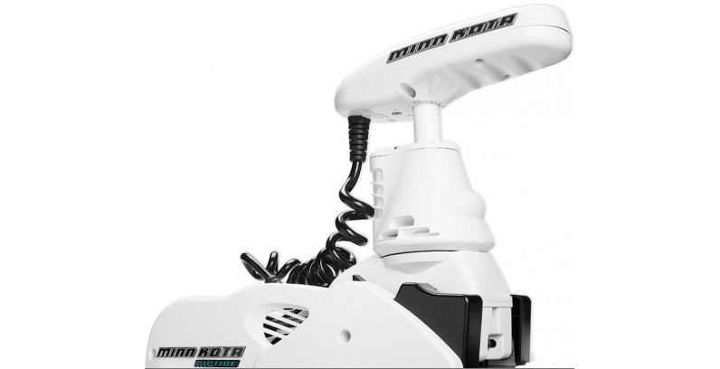


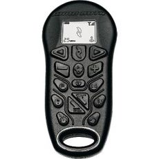
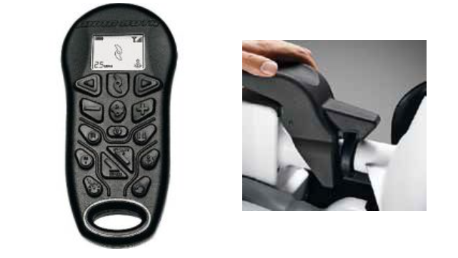
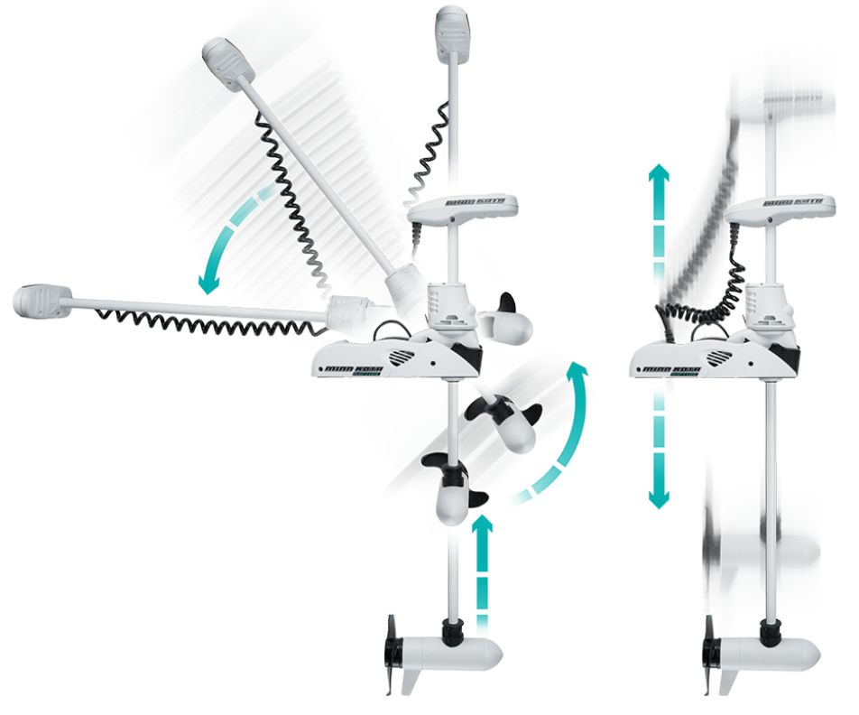
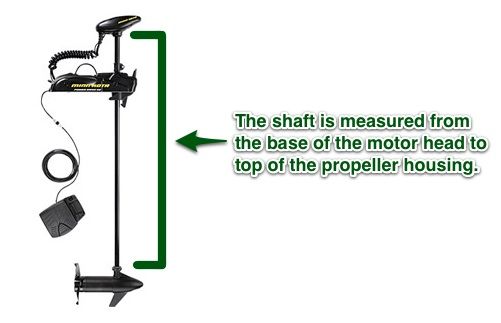

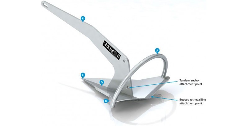
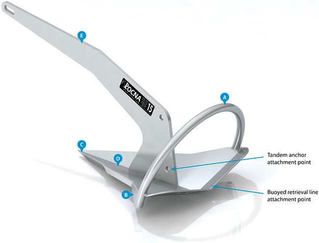
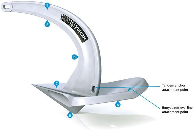
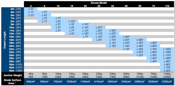
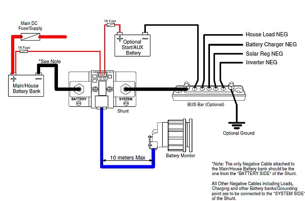
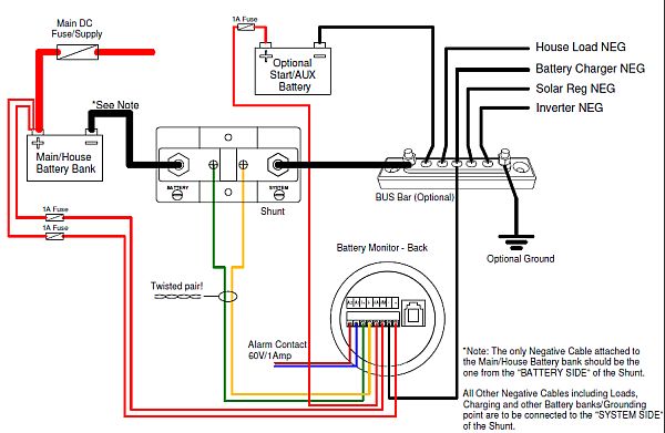
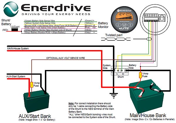
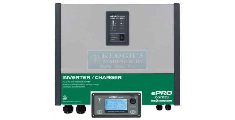
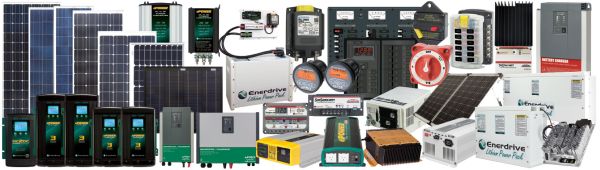


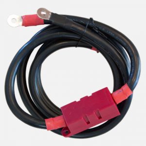
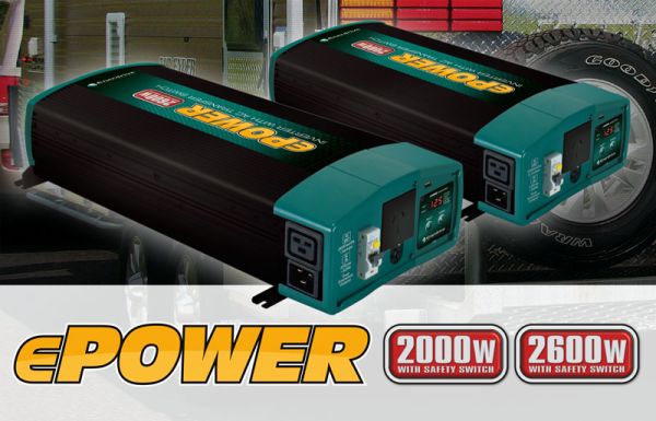
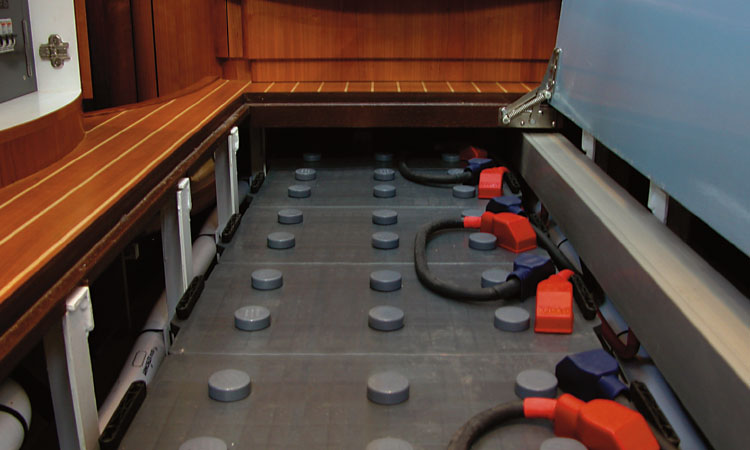
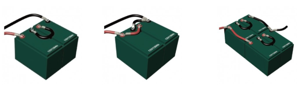
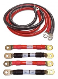
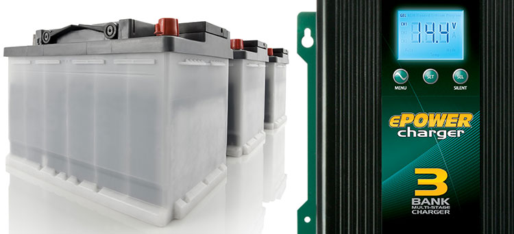
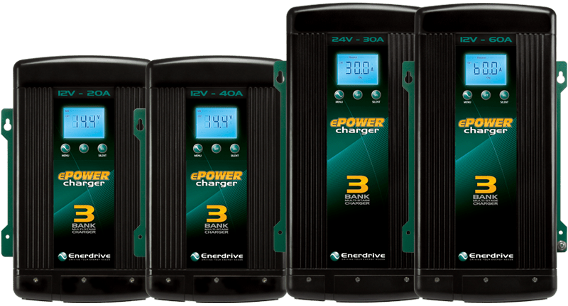
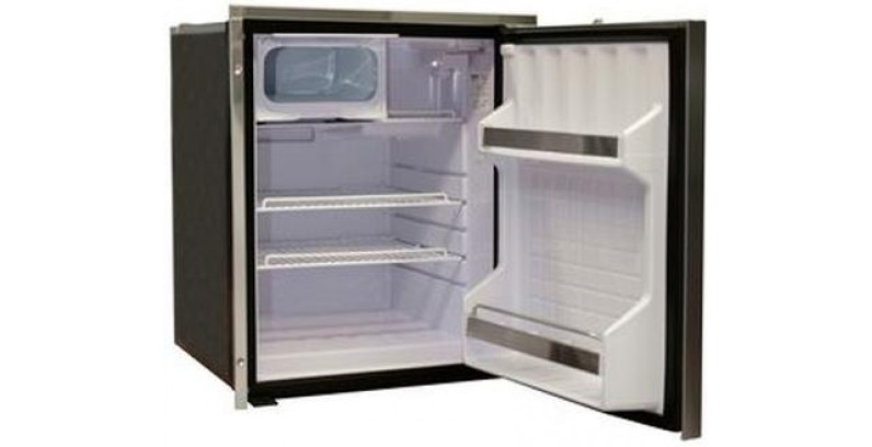
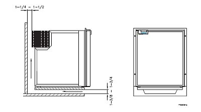
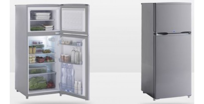
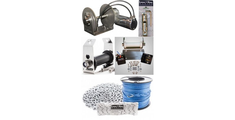
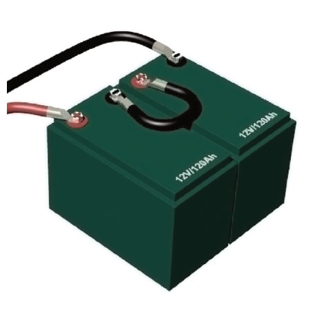
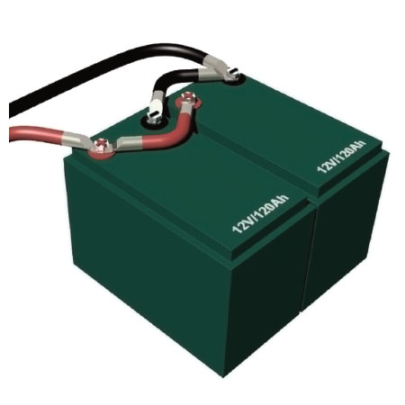
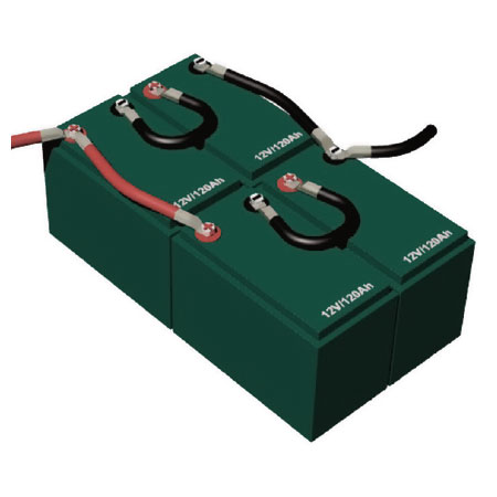